Download
1 / 29
290 likes | 291 Views
This presentation provides an overview of the J-PARC Complex and discusses the PTC-ORBIT code for studying single and multi-particle dynamics in the Main Ring. Topics covered include beam survival study, machine commissioning observations, resonance correction approach, and optimization of the machine performance.

E N D
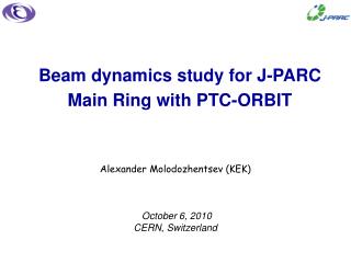
Beam dynamics study for J-PARC Main Ring with PTC-ORBIT Alexander Molodozhentsev (KEK) October 6, 2010 CERN, Switzerland
OUTLINE: • Overview of the J-PARC Complex • PTC-ORBIT code • Single particle dynamics study for MR with PTC • beam survival study (tune scan) • observations during the machine commissioning • resonance correction approach • Multi particle dynamics study (machine resonances • and space charge effects) for MR with PTC-ORBIT • optimization of the machine performance • tune scan study with/without resonance correction (prediction • and observations) A.Molodozhentsev (KEK)
Overview of the J-PARC Complex ‘Hadron’ area Main Ring ‘MLF’ facility ‘Neutrino’ line (T2K) RCS Linac A.Molodozhentsev (KEK)
Overview of the J-PARC Complex A.Molodozhentsev (KEK)
Overview of the J-PARC Complex A.Molodozhentsev (KEK)
Overview of the J-PARC Complex A.Molodozhentsev (KEK)
PTC-ORBIT code The Polymorphic Tracking Code (PTC) is a library of magnet routines programmed in Fortran90 that makes use of the Full Polymorphic Package (FPP). PTC implements symplectic integration and provides structures for the description of a beamline. A particle going through a beamline element sees only the local magnetic field, and PTC uses a local reference frame for describing that magnetic field—the frame most appropriate for the geometry of that type of element. To track through a series of beamline elements, PTC locates the elements with respect to each other using geometric transformations that connect the reference frame of one element to the reference frame of neighboring elements. • The two central features of PTC are: • Fortran90 types that allow the full three-dimensional placement of beamline • elements and the construction of non-standard accelerator topologies: colliders, • recirculators, dog-bones, and combinations of these topologies; • full usage of Taylor maps derived from the integrator for the computation of • lattice functions and other accelerator properties. A.Molodozhentsev (KEK)
PTC-ORBIT code In-depth discussions of all these concepts can be found in several publications by Étienne Forest: • Étienne Forest, “A Hamiltonian-free description of single particle dynamics for hopelessly complex periodic systems”, J. Math. Phys., 31(5):1133–1144, May 1990, DOI: 10.1063/1.528795; • Étienne Forest and Kohji Hirata, “A contemporary guide to beam dynamics”, Technical Report KEK-92-12, KEK, Tsukuba, Japan, August 1992; • Étienne Forest, “Locally accurate dynamical Euclidean group”, Phys. Rev. E, 55(4):4665–4674, April 1997, DOI: 10.1103/PhysRevE.55.4665; • Étienne Forest, Beam Dynamics: A New Attitude and Framework, volume 8 of The Physics and Technology of Particle and Photon Beams, Harwood Academic Publishers, Amsterdam, 1998; • Étienne Forest, “Geometric integration for particle accelerators”, J. Phys. A: Math. Gen., 39(19):5321–5377, May 2006, DOI: 10.1088/0305-4470/39/19/S03. Where to obtain PTC http://www.takafumi.org/etienne/ptc/ A.Molodozhentsev (KEK)
PTC-ORBIT code A.Molodozhentsev (KEK)
PTC-ORBIT code • Basic lattice preparation should be made by MAD8 • Alignment errors for different types of magnets should be • made inside of ORBIT A.Molodozhentsev (KEK)
PTC-ORBIT code The transverse space charge forces are evaluated as nonlinear kicks using the explicit second order PIC model and FFT. Coupling the longitudinal motion into the transverse tune space is determined by scaling the space-charge force on the given macro-particle according to the longitudinal charge density at its position in the bunch. Sympletic ‘Teapot’ tracker is used in ORBIT to propagate the macro-particles from one ‘space-charge’ node to another. A.Molodozhentsev (KEK)
PTC-ORBIT code IDEA (discussed during HB’06 workshop): … create the same UNIVERSE for a realistic machine model including: basic focusing lattice analysis single particle dynamics study including effects of nonlinear elements lattice resonance corrections multi particle dynamics study (space charge effects in combination with lattice resonances, caused by the machine imperfections) REALIZATION( during 2007, SNS-KEK collaboration ): PTC part realistic lattice description, including magnet’s alignment; acceleration process; resonance correction approaches; symplectic tracker between the ‘space charge’ nodes; particle losses in machine aperture around the machine; … many other items on request ORBIT part space charge kick at the ‘space charge’ node; multi particle diagnostics; aperture and collimations; … other possibilities of the code should be checked A.Molodozhentsev (KEK)
PTC-ORBIT(MPI) code Convergence study for MR Multi-processor systems • the number of the azimuthal integration steps; • the number of macro-particles; • the spatial resolution, the grid parameter • for the FFT algorithm. Naz = 256 (128) Nmp ~ 200e3 NFFT = 128128 NSC_NODE ~ 1500 KEK Super Computer system: HITACHI SR11000 (8.4GFlops/CPU) A.Molodozhentsev (KEK)
PTC-ORBIT(MPI) code How does it look ? • STEP1 (in combination with MADX): • Machine description … by MADX or by PTC itself • Machine study … lattice properties (linear / nonlinear)… tune variation • Chromaticity correction … • Full power of MADX and/or PTC can be used at this level • STEP2 (PTC or MADX-PTC): • Single particle dynamics study … • Resonance observation and correction … • Preparation (by PTC) for the multi particle tracking by PTC-ORBIT STEP3 (PTC-ORBIT): Multi particle dynamics without/with the space charge … all possibilities of ORBIT can be used … in principal … A.Molodozhentsev (KEK)
Single particle dynamics study for MR with PTC (MADX/PTC) A.Molodozhentsev (KEK)
Single particle dynamics study for MR with PTC • The computational model of the MR focusing structure has been developed by using all known data of the field measurements of each individual magnet of MR (MADX/PTC code) and the injection dog-leg, created by the bump-magnets (including edge-focusing). • List of measured field components of different MR magnets, used for the realistic MR lattice description: • up to the sextupole components {BM}96 • up to the 5th order components {QM}216 • up to the 8th order {SxM}72. • field leakage of septum magnets … • Measured alignment and strength errors of each magnet . A.Molodozhentsev (KEK)
Main Ring tune-scan study‘zero’ beam intensity (4×10¹¹ ppb) ICFA HB’10 • Single particle dynamics: • Dynamic aperture > 150 • Beam Survival at MR collimator Tune-scan study (RUN #27- #28) November 2009 # Realistic MR imperfection # HCODmax < ± 2mm / VCODmax < ± 1mm # Chromaticity correction # ON&OFF momentum # Short-term tracking (4000 turns) # VRF = 80kV (h=9) # MR Scraper = 60 # ‘PTC’ code # ‘DC’ mode … T capture = 2sec # Beam transmission during 1.9 sec # Survival rate: p3/p2 40 msec # Corrected COD: HCOD < ± 2mm / VCOD < ± 1mm # Beam intensity 4×10¹¹ pp bunch # ‘Direct’ injection with chromaticity correction # ‘Fast extraction’ scenario • Candidates of the ‘bare’ working points significant particle losses: [1,1,43], [3,0,67] A.Molodozhentsev (KEK)
ICFA HB’10 • Main Ring tune-scan study‘zero’ beam intensity (4×10¹¹ ppb) A.Molodozhentsev (KEK)
ICFA HB’10 • Main Ring resonance observation and correction (model) • ‘Sum’ linear coupling resonance [1,1,43] • Sources for MR: • {QM} measured alignment (XY-tilt) … QM : 1 < 1×10⁻⁴ rad • VCOD at the MR chromatic sextupole magnets… < ± 1 mm Qx+Qy=43 Main Ring computational model (based on PTC) • Local linear decoupling by using 4 independent skew quads • Global linear decoupling by using 2 or 4 independent skew quads Local linear decoupling mechanism: - Based on the matrix decoupling at the point of observation … Global linear decoupling mechanism: - Based on minimization a ‘Ripken’ lattice function summed around the ring … A.Molodozhentsev (KEK)
ICFA HB’10 • Main Ring resonance observation and correction (model) Qx+Qy=43 • ‘Lattice’ resonance correction (single particle dynamics / PTC) Before yx ~ d<yx>/dI After the ‘global decoupling Qx ~ 22.21 Qy ~ 20.80 [1,1,43] resonance • (a1L) < 5% (k1L) • -beat < 6% • Coherent response of the beam with the space charge effects (PTC-ORBIT) Spectrum analysis of the <xy> coherent mode MR realistic model Qx = 22.27 Qy = 20.82 RCS 6D beam 1.8kW/bunch VRF = 120kV Bf ~ 0.16 QINC ~ -0.15 After the ‘global decoupling Before A.Molodozhentsev (KEK)
ICFA HB’10 • Main Ring resonance observation and correction Qx+Qy=43 • … create the required skew quadrupole field component by using the local VERTICAL bump of the circulating orbit at the location of two sextupole magnets with the appropriate phase-advance to demonstrate ability to minimize the particle losses, caused by the [1,1,43] resonance. • … the global linear decoupling has been performed by using the MR computational model (PTC). • PREDICTION: thelocal vertical bump of the circulating orbit at the location of two appropriate • sextupole magnets for the chromaticity correction should be about (2÷3) mm. • Observation (‘zero’ beam intensity) BEFORE AFTER ‘Lattice’ tune: Qx = 22.20 Qy = 20.80 Survival rate ~ 95% * For real MR configuration it is not possible to make the local bump of the beam orbit without touching the nearest sextupole magnets … A.Molodozhentsev (KEK)
Multi particle dynamics study (machine resonances and space charge effects) for MR with PTC-ORBIT A.Molodozhentsev (KEK)
ICFA HB’10 MR operation with the moderate beam power:predictions & observation • Realistic 6D particle distribution from J-PARC RCS, including effects of the 3-50BT collimation system. • Realistic MR RF system (4 cavities): fundamental harmonic (h=9) with Vmax=45kV/cavity. Purpose: predict the ‘bare’ working point to provide minimum particle losses for injection & acceleration A.Molodozhentsev (KEK)
Main Ring tune-scan study:moderate beam power (100kW@30GeV) ICFA HB’10 MR lattice resonances and performed tune-scanning (simulations) to minimize the beam loss. ‘Conceptual’ space charge incoherent detuning (Bf ~ 0.15) for the case of the single harmonic RF system. • GOAL: minimization the particle losses during the injection process taken into • consideration the machine imperfection resonances and the low energy • space charge effects … to make predictions of the losses for different ‘bare’ tunes. A.Molodozhentsev (KEK)
Main Ring tune-scan study:moderate beam power (100kW@30GeV) ICFA HB’10 • Prediction #1 (injection) / PTC_ORBIT • Simulation conditions (~ 200’000mp): • 6D RCS beam • 3-50BT collimator @ 54 • Beam intensity 1.2e13 ppbunch • Global correction of [1,1,43] by using 2 skew quads • VRF = 80kV (h=9) … Bf ~ 0.18 • MR scraper acceptance = 60 • Matched injection (Transverse & COD) • H_CODmax ~ ± 3mm, V_CODmax ~ 1.5mm • full linear chromaticity correction 2Qx-2Qy=3 Coherent mode analysis [2,-2,3] [3,0,67] [1,1,43] <x2y2> <x3> <xy> A.Molodozhentsev (KEK)
Main Ring tune-scan study:moderate beam power (100kW@30GeV) ICFA HB’10 • Observation:RUN#31- #32 Qy = 20.75 • Measurement conditions: • RCS beam power 300kW • 3-50BT collimator OPEN • Beam intensity 1.3e13 ppbunch • [1,1,43] correction by local V_bump at 2SX • VRF = 80kV (h=9) … Bf ~ 0.18 • MR scraper acceptance = 60 • Matched injection (Transverse & COD) • H_CODmax ~ ± 3mm, V_CODmax ~ 1.5mm • full linear chromaticity correction • 1 batch operation (K2) 2Qx-2Qy=3 2Qx=45 3Qx=67 Minimum particle losses (3 batches): DCCT: K3/K2 = 0.987 (injection) P3/P2 = 0.983 (acceleration) A.Molodozhentsev (KEK)
Main Ring tune-scan study:moderate beam power (100kW@30GeV) ICFA HB’10 Demonstration of the ‘100kW equivalent’ MR operation has been performed successfully (June 7, 2010): • the extracted beam to the abort beam dump was 7.2×10¹³ proton per pulse with the six-bunch operation; including the [1,1,43] resonance correction; • the particle losses are localized at the collimation section during the injection&acceleration processes … the total loss is about 7.7×10¹¹, which corresponds to ~ 120W (as predicted). MR collimator = 60 Qx = 22.40 Qy = 20.75 A.Molodozhentsev (KEK)
Conclusions: • Predictions, made by using the computational model of J-PARC • Main Ring (MADX&PTC-ORBIT combined code), and experimental • results for the moderate beam power are in the reasonable • agreement. • Performed optimization of the J-PARC Main Ring performance allows • to provide the total particle losses ~ 120Watt during the injection and • acceleration processes (~ 0.12% from the beam power at 30GeV). • The developed computational model will be used to optimize the • J-PARC MR performance for the high beam power operation. Thank you for your attention ! A.Molodozhentsev (KEK)