Download
1 / 8
80 likes | 249 Views
ZTF Server Architecture. Roger Smith Caltech 2013-05-06. Requirements. R eadout 16 CCDs with 4 output channels at 1MHz per channel. Use standard host I/O port (USB2 is baseline). Transmission over optical fiber (for ground isolation and ~50m length)

E N D
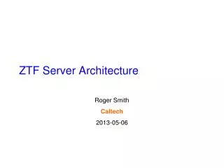
ZTF Server Architecture Roger Smith Caltech 2013-05-06
Requirements • Readout 16 CCDs with 4 output channels at 1MHz per channel. • Use standard host I/O port (USB2is baseline). • Transmission over optical fiber (for ground isolation and ~50m length) • Data transfers synchronized to readout; timing jitter << pixel time. • Requires data buffer to be at fiber receiver, not in controller. • This may be incompatible with using standard I/O port. If so the requirement is to make crosstalk very low from data link back to video chain. • Ample headroom on data rates and storage capacity everywhere. • Data storage sufficient for 20 (TBC) days. • Minimize development labor; preserve validity of early tests. • Fully parallel system is easiest to test. • Minimize costs for capital and ongoing support: • fewer servers each with multiple USB2 inputs, but now we need to test data rates as a function of number of links. • A solution is to test the multiple USB configuration soon after the single link is working.
P48 Control Room P48 Telescope MasterClk, Trigger USB -> Fiber Timing bd. Fiber -> USB2 CCD Server, Marshall ~160Mb/s 8ch * 16b * 1 MHz 95GB/night May be RAID for better data security (data redundancy and error checks) CCD Disk Video bd. USB -> Fiber Timing bd. Fiber -> USB2 CCD Server ~160Mb/s 8ch * 16b * 1 MHz 10.5 day/TB CCD Disk Video bd. 760 GB/day = 88 Mbit/s average. Communications 16 CCDs 8 CCD controllers USB -> Fiber Timing bd. Fiber -> USB2 CCD Server TBD Mbit/s ~160Mb/s 8ch * 16b * 1 MHz HPWREN CCD Disk Video bd. Ethernet
P48 Control Room P48 Telescope 380 GB/night for 8 CCDs MasterClk, Trigger USB -> Fiber Master Timing bd. Fiber -> USB CCD Server, Marshall ~160Mb/s 8ch * 16b * 1 MHz CCD Raid farm Video bd. USB -> Fiber Timing bd. Fiber -> USB CCD ~160Mb/s 8ch * 16b * 1 MHz CCD Video bd. For 16 CCDs, 758 GB/day = 88 Mbit/s average. Communications 16 CCDs 8 CCD controllers 380 GB/night for 8 CCDs USB -> Fiber Timing bd. Fiber -> USB CCD Server ??MB/s ~160Mb/s 8ch * 16b * 1 MHz 10.5 day/TB HPWREN CCD Raid Farm Video bd. Ethernet
Notes • Data is stored as multiple files per exposure, one file per CCD. Files are distributed across several disks. • Controller does not need to be modified as system size is scaled up. Just buy more fiber optic modems for USB links. • There are no data concentrator boards, and no GB Ethernet required in IFPAC as proposed initially by IUCAA. • Servers don’t need to be very fancy as load is distributed uses standard USB interfaces (several in parallel). • Disk is RAID more for data redundancy and error detection than for speed. • Disk capacity to hold weeks of data is not prohibitive. Automatically delete oldest when nearing full. This provides a backup/retransmit capability with low data management complexity.
Storage format • How to handle multiple amplifiers? • Multi-extension FITS with one extension per amplifier? • If conventional FITS then are overscan pixels in temporal order (middle of image)? • All images are read through 4 channels and the same way up. • File name: ZTFxyUTyyyymmdd_hhmmss • x = {1:4} (CCD position) • y = {1:4} • Using date and time to generate name avoids sequencing glitches (gaps or duplicates) that can be caused by system crashes. • How does PTF do it? • Headers .. A topic for another day. Controller software will generate headers with only controller specific content. More info will be added by separate post processing tasks.
Numeric format and compression The following are still under discussion at Caltech: • Files will need to be compressed. We are considering doing this during the initial FITS file write. • The “Tile Compression” format is in universal use at NOAO. This looks promising since: • It compresses the image within FITS while leaving the header readable without decompression. • Subarrays of the image can be decompressed without decompressing the whole file. • It is optimized for astronomical data. • Data rates in this presentation are based on 16 bit output from each video channel, but we have >16 bit dynamic range. Either the Digital CDS output will be converted to unsigned 16 bit floating point (probably 4 bits of exponent and 12 of mantissa) or 24 bit integers will be transmitted then compressed.
Data rates While the baseline design is for 12 CCDs in a swiss cross, we are looking at a design that allows expansion to 16 CCDs so these rates are sized to the latter. 1 Mpixel/s/ch * 4 ch/CCD * 2 CCD per controller * 16 bits/pixel = 16 MByte/s = 128 Mbit/s raw data rate *10/8 = 160 Mbit/s per USB link (out of 480 Mb/s capacity) If four USB links per server, data rate to its RAID = 64 MB/s. Total burst data rate = 128 MBs. Reading 9.5s out of every 35s, average night time rate = 34.7 MB/s. Observing 12 hours per day, average downlink rate = 17.3 MB/s = 173 Mb/s. (Headers & telemetry assumed to be negligible overheads.) Only mild compression (ie lossless) appears to be needed to fit into 150Mbit/s HPWREN throughput.