Download
1 / 38
380 likes | 500 Views
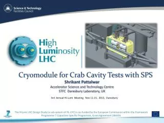
Impedance of Y-Chamber for SPS Crab cavity. By Phoevos Kardasopoulos Thanks to Benoit Salvant , Pei Zhang, Fred Galleazzi, Roberto Torres-Sanchez and Alick MacPherson Impedance Meeting Date: 14/04/14. Contents. Overview Methodology Review Existing Y-Chamber (COLDEX)

E N D
Impedance of Y-Chamber for SPS Crab cavity By Phoevos Kardasopoulos Thanks to Benoit Salvant, Pei Zhang, Fred Galleazzi, Roberto Torres-Sanchez and Alick MacPherson Impedance Meeting Date: 14/04/14
Contents • Overview • Methodology • Review Existing Y-Chamber (COLDEX) • Evaluation of Designs for Crab Cavities • Presentation of recommended impedance design • Issues Related to Bellows • Conclusions Objective of this talk: Present revised Y-chamber design for SPS crab cavity installation and seek approval from impedance group, so that the design can proceed to fabrication by the vacuum group.
Contents • Overview • Methodology • Review Existing Y-Chamber (COLDEX) • Evaluation of Designs for Crab Cavities • Presentation of recommended impedance design • Issues Related to Bellows • Conclusions
Overview • Y-Chamber’s purpose to switch objects in and out of the beam line.
Overview • Y-Chamber’s purpose to switch objects in and out of the beam line.
Overview • Current Y-Chamber: • Used by COLDEX. • Opening angle: 12 degrees. • Transverse displacement: 340mm. • Crab Cavities: • Opening angle: 16 degrees. • Transverse displacement: 510mm. • Expected number of cycles(in and out) = O(1000). • Redesign needed: • Mechanical redesign needed to accommodate Crab Cavities. • Take opportunity to redesign Y-Chamber to reduce impedance. • Mechanical design must have required reliability.
Previous Research • Previous research has been conducted: • B. Spataroet al • Impedance of the LHC recombination chambers. LHC Project Note 254. 03/05/2001 • On trapped modes in the LHC recombination chambers: experimental results. LHC Project Note 254. LHC Project Note 266. 14/08/2001 • LHC Recombination chamber. • Possibility of trapped modes above the cut off frequency.
Contents • Overview • Methodology • Review Existing Y-Chamber (COLDEX) • Evaluation of Designs for Crab Cavities • Presentation of recommended impedance design • Issues Related to Bellows • Conclusions
Methodology • Initial 12o Y-chamber model received from Benoit. • CST used to perform simulations on the models. • Selection criteria: Based on CST simulations • High frequency : Frequency domain Eigenmode solver. • Low frequency: Time domain Wakefield solver • Results for new designs compared to baseline results of initial Y-chamber model.
Methodology – High Frequency • Look at high frequency modes excited by the beam. • Evaluate shunt impedances. • Eigenmode solver. • Shunt impedances – CST post processing • Circular convention 2. • Evaluate impedance of transverse modes • Panofsky-Wenzel theorem – Only true for symmetric structures. • d = transverse displacement of integration path in cavity axis • Integration path offset by: d = ±5mm, ± 7mm, and ± 10mm. • MATLAB script to fit a parabolic shape, and take the coefficient of the linear term.
Methodology – Low Frequency • Use time domain solver and look at imaginary part of impedance for different source-wake bunch configurations • Separate simulations for the monopole, dipole, and quadrupole. Source bunch wake bunch (1) (2) (3) (4) (5) 1)Monopole - Beam and test beam on the beam axis 2)Horizontal Dipolar - Beam offset from the beam axis in x 3)Horizontal Quadrupolar - Test beam offset from the beam axis in x 4)Vertical Dipolar - Beam offset from the beam axis in y 5)Vertical Quadrupolar - Test beam offset from the beam axis in y
Methodology – Low Frequency • Effective longitudinal impedance: • n= f/frev • Effective transverse impedance: • Transverse impedance needs to be weighted by : • =0.65
Contents • Overview • Methodology • Review Existing Y-Chamber (COLDEX) • Evaluation of Designs for Crab Cavities • Presentation of recommended impedance design • Issues Related to Bellows • Conclusions
Current Y-Chamber • 12 degree version currently installed at COLDEX at SPS LSS4 • There are 3 of these currently in the SPS. • Two at LSS4, COLDEX(Crab Cavity) testing area. • Legacy design: Reasons behind design are unclear.
Current Y-Chamber Two Models: . Baseline model. As-Installed Stainless Steel Boundaries All Beam pipe connection inner diameter = 155 mm
Current Y-Chamber Two Models: Baseline model. As-Installed Stainless Steel Boundaries All Beam pipe connection inner diameter = 155 mm
Eigenmode Results – Simple Y-Chamber Cut off frequency at 1.48 GHz Waveguide theory, Pipe radius 77.5mm Results from Eigenmode Simulations 1 Transverse mode identified 48 kOhms/m at 1.40 GHz
Wakefield Solver - Simple Y-Chamber Results from Eigenmode Simulations
Low Frequency Transverse Bunch length = 300 Charge =1e-9 Wakelength = 20000 Direct Testbeams CST Convention: Inductive impedance is -ve (d=5mm) 0.5 kOhms/m
Low Frequency Transverse Bunch length = 300 Charge =1e-9 Wakelength = 20000 Direct Testbeams = 0.48 kOhms/m
Low Frequency Longitudinal Y-Chamber ≈ 2.8 ± 0.2 mOhms
12 Degree Model Comparison SPS ≈ 20 MOhms/m
12 Degree Model Comparison SPS: Total Longitudinal 5 Ohms Total Transverse 20MOhms/m
Contents • Overview • Methodology • Review Existing Y-Chamber (COLDEX) • Evaluation of Designs for Crab Cavities • Presentation of recommended impedance design • Issues Related to Bellows • Conclusions
Alternate Designs Analysed All Designs: 16 Degree angle, stainless steel boundaries, 155mm pipe diameter • Scaled up with undulations. • Scaled up of 12 degree. • Provided by F. Galleazzi. • Ellipsoid Conical. • Proposed.
High Frequency Transverse Impedance Proposed Design - No significant transverse modes why?
Low Frequency Impedance Comparisons SPS: 5 Ohms Longitudinal 20MOhms Transverse
Candidate Design Question: Is this design acceptable for the impedance working group? Question: What other aspects are important, aperture? Question: Can we proceed to develop mechanical design with vacuum group?
Contents • Overview • Methodology • Review Existing Y-Chamber (COLDEX) • Evaluation of Designs for Crab Cavities • Presentation of recommended impedance design • Issues Related to Bellows • Conclusions
Bellows Are there issues with the bellows? Suggested by Cedric Garion TE-VSC-DLM
Bellow Impedance • Analytical Mode l- At high energy (http://cdsweb.cern.ch/record/118026/files/p1.pdf) (Valid up to first cut off frequency) Effective Impedance ≈0.65 mOhms
Bellow Impedance Cut off frequency at 1.47 GHz Waveguide theory, Pipe radius 78mm Should we be worried at we approach cut-off Effective Impedance ≈0.65 mOhms
Bellow Impedance • Transverse Impedance: • (Handbook of Accelerator Physics and Engineering, pg. 258, A. Wu. Choa) • 3.12 mOhms/m
Contents • Overview • Methodology • Review Existing Y-Chamber (COLDEX) • Evaluation of Designs for Crab Cavities • Presentation of recommended impedance design • Issues Related to Bellows • Conclusions
Conclusions • Current 12 degree Y-Chamber has been modelled in CST. • Impedances have been calculatedcross checked with previous calc.. • Consistency cross check between time and frequency domain. • Crab cavity Y-Chambers designs • 4 models have been modelled & impedances calculated. • Results • Scaled up version of current Y-Chamber has increased impedance. • Reducing the volume reduces the impedance. • Candidate design: • Shunt impedance: • lowest significant: 3.92 kOhms @ 1.12 GHz • Most significant:: 5.25 kOhms @ 1.39 GHz • No transverse mode below cut off • Contribution from bellows: TE-VSC Design has negligible Impedance • Next step: Can impedance working group endorse Y-Chamber design for next step.