Download
1 / 26
260 likes | 271 Views
Systems. Technical. Operational. Modeling DoDAF Compliant Architectures. An Architecture Development Process. Stakeholder. requirements. Program. Operational. Installation. CUSTOMER. definition. engineering. & validation. system. Single project at. Reporting, metrics &. Proposed.

E N D
Systems Technical Operational Modeling DoDAF Compliant Architectures
Stakeholder requirements Program Operational Installation CUSTOMER definition engineering & validation system Single project at Reporting, metrics & Proposed management control the systems level characteristics System Integrated Integration SUPPLIERS requirements Product Architectural & system definition design engineering verification Delivered Allocated Reporting, metrics & Proposed sub-systems requirements Multiple projects characteristics management control System Integration Integrated requirements “Local” user & Architectural Product configuration & definition organizational design engineering items verification requirements Delivered Proposed sub-systems Reporting, metrics & characteristics Allocated management control requirements Multiple projects Integrated System Integration configuration requirements “Local” user & Architectural Product & items definition organizational design engineering verification requirements Delivered Proposed components Allocated characteristics Reporting, metrics & requirements management control Component developments Component Component Components Component requirements build & test design Traditional Systems Engineering
Statement of Need Program Operational Installation engineering & validation Capability Single project at Reporting, metrics & Proposed management control the SoS level characteristics Integrated Integration Operational Concept Program Architectural & SoS design engineering verification Delivered Allocated Reporting, metrics & Proposed systems requirements Multiple projects characteristics management control System Integration Integrated System requirements “Local” user & Architectural Product & definition organizational design engineering verification requirements Delivered Proposed sub-systems Reporting, metrics & characteristics Allocated management control requirements Multiple projects Integrated System Integration configuration requirements “Local” user & Architectural Product & items definition organizational design engineering verification requirements Delivered Proposed components Allocated characteristics Reporting, metrics & requirements management control Component developments Component Component Components Component requirements build & test design Systems Engineering and Architecture based acquisition and development CUSTOMER SUPPLIERS
Requirements layer Modelling layer Requirements layer Requirements layer Requirements layer Systems Engineering is a Club Sandwich Our apologies to Forrest Gump! Modelling layer Modelling layer
Requirements layer Modelling layer Requirements layer Modelling layer Requirements layer Modelling layer Requirements layer Models Bridge Layers of RequirementsTraditional Systems Engineering Statement of need e.g Goal / Usage modeling Stakeholder requirements Functional modeling e.g. Functional modeling System requirements Functional modeling Functional modeling e.g. Performance modeling Architectural design
Requirements layer Modelling layer Requirements layer Modelling layer Requirements layer Modelling layer Requirements layer Models Bridge Layers of RequirementsDoDAF Perspective Statement of need e.g Goal / Usage modeling Capability requirements Functional modeling e.g. Functional modeling Architectural Design Functional modeling Functional modeling e.g. Performance modeling System Requirements
The Role of Models Models can be used to complement requirements management at each of the different layers and are useful in a number of ways: • Architecture modeling adds formality to the design process that lies between each layer of requirement • The architecture model promotes an active understanding of the details in large requirements documents • The design rationale gathered around the architecture model becomes the rationale for traceability between layers of requirements • The structure of the architecture model can be used to give structure to the requirements document • The architecture model is the basis for: • costing, interoperability analysis, partitioning to different development teams, scheduling (WBS), analysis of alternatives, early validation, and risk management.
Systems Modeling Techniques • A very wide range of very domain-specific modeling techniques may be used to aid systems design: • Aerodynamic models using wind tunnels • Safety, reliability and maintainability models • Weight distribution models • Network performance models using queuing theory • Although many models are necessarily domain-specific, every system has aspects which can be modeled using a basic approach such as DoDAF. • A basic architecture model that proves that the architecture provides the desired capabilities (structure and behavior) should be done prior to committing resources to more detailed modeling and simulation.
Activities in the Systems Engineering Process • There are two major activities in the Basic systems engineering process: • To analyze the input requirements and create a model • To derive the output requirements from the model • These steps are applied recursively through the layers.
Requirements Requirements Requirements Output Input Requirements Requirements Requirements documents documents documents Design Requirements Requirements documents documents documents Basic Process for the Data Model Analyze & Model Derive Requirements
Design Design Design documents documents Basic Process for the Data Model Showing Traceability Requirements Input Requirements documents documents Requirements Analyze & 1 Model 3 Derive 2 Requirements 4 Requirements Output Requirements documents Requirements documents Design Design Design (in layer below) documents documents
Top-Level Activity Model for Developing DoDAF Architectures Analyze & Model
First Level of Decomposition of Activity Model for Developing Architectures
Simplified Structured Analysis Workflow for Developing the Operational View
Simplified Structure Analysis Workflow for Developing the System View(and integrating to OV)
Simplified Workflow for Developing the Technical Standards View(and integrating)
Object Oriented Workflow • Structure Analysis decomposes behaviour and structure separately, then does an explicit allocation of behaviour to structure. • Data, Behaviour and Structure are considered independently • Activity model (OV-5) focus • OO Methods focus on objects (the things that possess behaviour and structure) and does implicit allocation of behaviour to structure. • Data, Behaviour and Structure are considered simultaneously • Main goal is to describe re-useable objects that encapsulate behaviour and structure. • Lends itself to iterative development and resilient architectures. • Event Trace (OV-6c) focus • The Case Study uses a blend of the two methodologies (as does DoDAF itself).
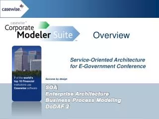
Telelogic Enterprise Architect - Objective • Use integrated, best of breed tools • Map work products to tool that best supports them • Provide domain-specific menus and help • Make it easy to adopt • Leverage automation • Reports, templates and model execution • Model-based tool repository • Easy model development and update with real-time checking • Standards-based • Proven, standard notation, executable and scalable • Methodology Independent: OO or SADT or a combination • Direct hand-off to systems engineering and software engineering
Telelogic Enterprise Architect - What is it? • A TAU G2 DoDAF profile and set of templates in DOORS to support and simplify: • Production of architecture descriptions • Analysis of architecture descriptions • Reporting
Telelogic Enterprise Architect - Benefits • Comprehensive support of all views and products • Automated consistency between products • Automatic generation of selected products (e.g. OV-3, OV-6c, SV-3, SV-5, SV-6, SV-10c) • Custom icons to enhance communication • Meta-model, based on CADM, drives the tool to speak the language of the domain • Executable Models • Verify behaviour and completeness early • Integration from requirements and standards, through enterprise architecture, to systems designs, development and acquisition • Complete traceability easy to establish and maintain (“Link as you think”) • Impact and gap analysis • Same tool for System Architecture, Software Design, Software Implementation.
Status & Analysis for Managers Bidder Responses& Score Cardsfor Assessors Criteria Definition for Preparers Smooth Handoff to Procurement
Application Smooth Handoff to Engineering Architecture Modeling Reuse Systems Modeling Software Design Traceability
Thank You • I hope you found this both educational and enjoyable. • All comments, questions and suggestions welcome. • Greg.Gorman@Telelogic.com