Download
1 / 90
900 likes | 1.08k Views
Module 16: Distributed System Structures. Chapter Objectives. To provide a high-level overview of distributed systems and the networks that interconnect them To discuss the general structure of distributed operating systems. Motivation.

E N D
Chapter Objectives • To provide a high-level overview of distributed systems and the networks that interconnect them • To discuss the general structure of distributed operating systems
Motivation • Distributed system is collection of loosely coupled processors interconnected by a communications network • Processors variously called nodes, computers, machines, hosts • Site is location of the processor • Reasons for distributed systems • Resource sharing • sharing and printing files at remote sites • processing information in a distributed database • using remote specialized hardware devices • Computation speedup – load sharing • Reliability – detect and recover from site failure, function transfer, reintegrate failed site • Communication – message passing
Types of Distributed Operating Systems • Network Operating Systems • Distributed Operating Systems
Network-Operating Systems • Users are aware of multiplicity of machines. Access to resources of various machines is done explicitly by: • Remote logging into the appropriate remote machine (telnet, ssh) • Remote Desktop (Microsoft Windows) • Transferring data from remote machines to local machines, via the File Transfer Protocol (FTP) mechanism
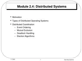
Distributed-Operating Systems • Users not aware of multiplicity of machines • Access to remote resources similar to access to local resources • Data Migration – transfer data by transferring entire file, or transferring only those portions of the file necessary for the immediate task • Computation Migration – transfer the computation, rather than the data, across the system
Distributed-Operating Systems (Cont.) • Process Migration – execute an entire process, or parts of it, at different sites • Load balancing – distribute processes across network to even the workload • Computation speedup – subprocesses can run concurrently on different sites • Hardware preference – process execution may require specialized processor • Software preference – required software may be available at only a particular site • Data access – run process remotely, rather than transfer all data locally
Network Structure • Local-Area Network (LAN) – designed to cover small geographical area. • Multiaccess bus, ring, or star network • Speed 10 – 100 megabits/second • Broadcast is fast and cheap • Nodes: • usually workstations and/or personal computers • a few (usually one or two) mainframes
Network Types (Cont.) • Wide-Area Network (WAN) – links geographically separated sites • Point-to-point connections over long-haul lines (often leased from a phone company) • Speed 1.544 – 45 megbits/second • Broadcast usually requires multiple messages • Nodes: • usually a high percentage of mainframes
Network Conversations End: Requester End: Replier
Network Topology • The various topologies are depicted as graphs whose nodes correspond to sites • An edge from node A to node B corresponds to a direct connection between the two sites • The following six items depict various network topologies
Communication Protocol • Physical layer – handles the mechanical and electrical details of the physical transmission of a bit stream • Data-link layer – handles the frames, or fixed-length parts of packets, including any error detection and recovery that occurred in the physical layer • Network layer – provides connections and routes packets in the communication network, including handling the address of outgoing packets, decoding the address of incoming packets, and maintaining routing information for proper response to changing load levels The communication network is partitioned into the following multiple layers:
Communication Protocol (Cont.) • Transport layer – responsible for low-level network access and for message transfer between clients, including partitioning messages into packets, maintaining packet order, controlling flow, and generating physical addresses • Session layer – implements sessions, or process-to-process communications protocols • Presentation layer – resolves the differences in formats among the various sites in the network, including character conversions, and half duplex/full duplex (echoing) • Application layer – interacts directly with the users’ deals with file transfer, remote-login protocols and electronic mail, as well as schemas for distributed databases
User Data IP hdr TCP segment Linkhdr Network segment MAC hdr MAC trlr Link layer segment MAC frame TCP/IP View of Encapsulation TCP hdr
TCP/IP Message Flow HTTP messages Application Layer Application Layer TCP segments Transport Layer Transport Layer Service Access Point IP packets Network Layer Network Layer Ethernet frames Data Link Layer Data Link Layer Interface Physical Layer Physical Layer bits
server browser TCP TCP Network Network Link Link Phys Phys Up and Down the Layers HTTP msg TCP segment pkt Network Link Link frm Phy Phys bits Relay Node Open System B Open System A router
Communication Structure • Naming and name resolution - How do two processes locate each other to communicate? • Routing strategies - How are messages sent through the network? • Connection strategies - How do two processes send a sequence of messages? • Contention - The network is a shared resource, so how do we resolve conflicting demands for its use? The design of a communication network must address four basic issues:
Naming and Name Resolution • Name systems in the network • Address messages with the process-id • Identify processes on remote systems by <host-name, identifier> pair • Domain name service (DNS) – specifies the naming structure of the hosts, as well as name to address resolution (Internet)
Root DNS Servers org DNS servers edu DNS servers com DNS servers poly.edu DNS servers umass.edu DNS servers pbs.org DNS servers yahoo.com DNS servers amazon.com DNS servers Distributed, Hierarchical Database client wants IP for www.amazon.com; 1st approx: • client queries a root server to find com DNS server • client queries com DNS server to get amazon.com DNS server • client queries amazon.com DNS server to get IP address for www.amazon.com Application 2-25
contacted by local name server that can not resolve name root name server: contacts authoritative name server if name mapping not known gets mapping returns mapping to local name server DNS: Root name servers a Verisign, Dulles, VA c Cogent, Herndon, VA (also LA) d U Maryland College Park, MD g US DoD Vienna, VA h ARL Aberdeen, MD j Verisign, ( 21 locations) k RIPE London (also 16 other locations) i Autonomica, Stockholm (plus 28 other locations) m WIDE Tokyo (also Seoul, Paris, SF) e NASA Mt View, CA f Internet Software C. Palo Alto, CA (and 36 other locations) 13 root name servers worldwide b USC-ISI Marina del Rey, CA l ICANN Los Angeles, CA Application 2-26
Routing Strategies • Fixed routing - A path from A to B is specified in advance; path changes only if a hardware failure disables it • Since the shortest path is usually chosen, communication costs are minimized • Fixed routing cannot adapt to load changes • Ensures that messages will be delivered in the order in which they were sent • Virtual circuit - A path from A to B is fixed for the duration of one session. Different sessions involving messages from A to B may have different paths • Partial remedy to adapting to load changes • Ensures that messages will be delivered in the order in which they were sent
Routing Strategies (Cont.) • Dynamic routing - The path used to send a message form site A to site B is chosen only when a message is sent • Usually a site sends a message to another site on the link least used at that particular time • Adapts to load changes by avoiding routing messages on heavily used path • Messages may arrive out of order • This problem can be remedied by appending a sequence number to each message
Connection Strategies • Circuit switching - A permanent physical link is established for the duration of the communication (i.e., telephone system) • Message switching - A temporary link is established for the duration of one message transfer (i.e., post-office mailing system) • Packet switching - Messages of variable length are divided into fixed-length packets which are sent to the destination • Each packet may take a different path through the network • The packets must be reassembled into messages as they arrive • Circuit switching requires setup time, but incurs less overhead for shipping each message, and may waste network bandwidth • Message and packet switching require less setup time, but incur more overhead per message
Circuit Switching C B D A E
Packet Switching C B D A E
Contention • CSMA/CD - Carrier sense with multiple access (CSMA); collision detection (CD) • A site determines whether another message is currently being transmitted over that link. If two or more sites begin transmitting at exactly the same time, then they will register a CD and will stop transmitting • When the system is very busy, many collisions may occur, and thus performance may be degraded • CSMA/CD is used successfully in the Ethernet system, the most common network system Several sites may want to transmit information over a link simultaneously. Techniques to avoid repeated collisions include:
Failure Detection • Detecting hardware failure is difficult • To detect a link failure, a handshaking protocol can be used • Assume Site A and Site B have established a link • At fixed intervals, each site will exchange an I-am-up message indicating that they are up and running • If Site A does not receive a message within the fixed interval, it assumes either (a) the other site is not up or (b) the message was lost • Site A can now send an Are-you-up? message to Site B • If Site A does not receive a reply, it can repeat the message or try an alternate route to Site B
Failure Detection (cont) • If Site A does not ultimately receive a reply from Site B, it concludes some type of failure has occurred • Types of failures:- Site B is down - The direct link between A and B is down- The alternate link from A to B is down - The message has been lost • However, Site A cannot determine exactly why the failure has occurred
Reconfiguration • When Site A determines a failure has occurred, it must reconfigure the system: 1. If the link from A to B has failed, this must be broadcast to every site in the system 2. If a site has failed, every other site must also be notified indicating that the services offered by the failed site are no longer available • When the link or the site becomes available again, this information must again be broadcast to all other sites
Background • Distributed file system (DFS) – a distributed implementation of the classical time-sharing model of a file system, where multiple users share files and storage resources • A DFS manages set of dispersed storage devices • Overall storage space managed by a DFS is composed of different, remotely located, smaller storage spaces • There is usually a correspondence between constituent storage spaces and sets of files
DFS Structure • Service – software entity running on one or more machines and providing a particular type of function to a priori unknown clients • Server – service software running on a single machine • Client – process that can invoke a service using a set of operations that forms its client interface • A client interface for a file service is formed by a set of primitive file operations (create, delete, read, write) • Client interface of a DFS should be transparent, i.e., not distinguish between local and remote files
Naming and Transparency • Naming – mapping between logical and physical objects • Multilevel mapping – abstraction of a file that hides the details of how and where on the disk the file is actually stored • A transparent DFS hides the location where in the network the file is stored • For a file being replicated in several sites, the mapping returns a set of the locations of this file’s replicas; both the existence of multiple copies and their location are hidden
Naming Structures • Location transparency – file name does not reveal the file’s physical storage location • Location independence – file name does not need to be changed when the file’s physical storage location changes
Remote File Access • Remote-service mechanism is one transfer approach • Reduce network traffic by retaining recently accessed disk blocks in a cache, so that repeated accesses to the same information can be handled locally • If needed data not already cached, a copy of data is brought from the server to the user • Accesses are performed on the cached copy • Files identified with one master copy residing at the server machine, but copies of (parts of) the file are scattered in different caches • Cache-consistency problem – keeping the cached copies consistent with the master file • Could be called network virtual memory
Cache Location – Disk vs. Main Memory • Advantages of disk caches • More reliable • Cached data kept on disk are still there during recovery and don’t need to be fetched again • Advantages of main-memory caches: • Permit workstations to be diskless • Data can be accessed more quickly • Performance speedup in bigger memories • Server caches (used to speed up disk I/O) are in main memory regardless of where user caches are located; using main-memory caches on the user machine permits a single caching mechanism for servers and users
Cache Update Policy • Write-through – write data through to disk as soon as they are placed on any cache • Reliable, but poor performance • Delayed-write – modifications written to the cache and then written through to the server later • Write accesses complete quickly; some data may be overwritten before they are written back, and so need never be written at all • Poor reliability; unwritten data will be lost whenever a user machine crashes • Variation – scan cache at regular intervals and flush blocks that have been modified since the last scan • Variation – write-on-close, writes data back to the server when the file is closed • Best for files that are open for long periods and frequently modified
Consistency • Is locally cached copy of the data consistent with the master copy? • Client-initiated approach • Client initiates a validity check • Server checks whether the local data are consistent with the master copy • Server-initiated approach • Server records, for each client, the (parts of) files it caches • When server detects a potential inconsistency, it must react
Stateful File Service • Mechanism • Client opens a file • Server fetches information about the file from its disk, stores it in its memory, and gives the client a connection identifier unique to the client and the open file • Identifier is used for subsequent accesses until the session ends • Server must reclaim the main-memory space used by clients who are no longer active • Increased performance • Fewer disk accesses • Stateful server knows if a file was opened for sequential access and can thus read ahead the next blocks
Stateless File Server • Avoids state information by making each request self-contained • Each request identifies the file and position in the file • No need to establish and terminate a connection by open and close operations
Distinctions Between Stateful & Stateless Service • Failure Recovery • A stateful server loses all its volatile state in a crash • Restore state by recovery protocol based on a dialog with clients, or abort operations that were underway when the crash occurred • Server needs to be aware of client failures in order to reclaim space allocated to record the state of crashed client processes (orphan detection and elimination) • With stateless server, the effects of server failure sand recovery are almost unnoticeable • A newly reincarnated server can respond to a self-contained request without any difficulty
Distinctions (Cont.) • Penalties for using the robust stateless service: • longer request messages • slower request processing • additional constraints imposed on DFS design • Some environments require stateful service • A server employing server-initiated cache validation cannot provide stateless service, since it maintains a record of which files are cached by which clients • UNIX use of file descriptors and implicit offsets is inherently stateful; servers must maintain tables to map the file descriptors, and store the current offset within a file
File Replication • Replicas of the same file reside on failure-independent machines • Improves availability and can shorten service time • Naming scheme maps a replicated file name to a particular replica • Existence of replicas should be invisible to higher levels • Replicas must be distinguished from one another by different lower-level names • Updates – replicas of a file denote the same logical entity, and thus an update to any replica must be reflected on all other replicas • Demand replication – reading a nonlocal replica causes it to be cached locally, thereby generating a new nonprimary replica
Chapter 18 Distributed Coordination • Event Ordering • Mutual Exclusion • Atomicity • Concurrency Control • Deadlock Handling • Election Algorithms