Download
1 / 34
340 likes | 362 Views
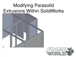
WORKSHOP 15 PARASOLID MODELING. WS15- 1. NAS120, Workshop 15, November 2003. Problem Description Create a parasolid model of a tension fitting using a number of the parasolid tools in MSC.Patran. Suggested Exercise Steps Create a new database for the tension fitting model.

E N D
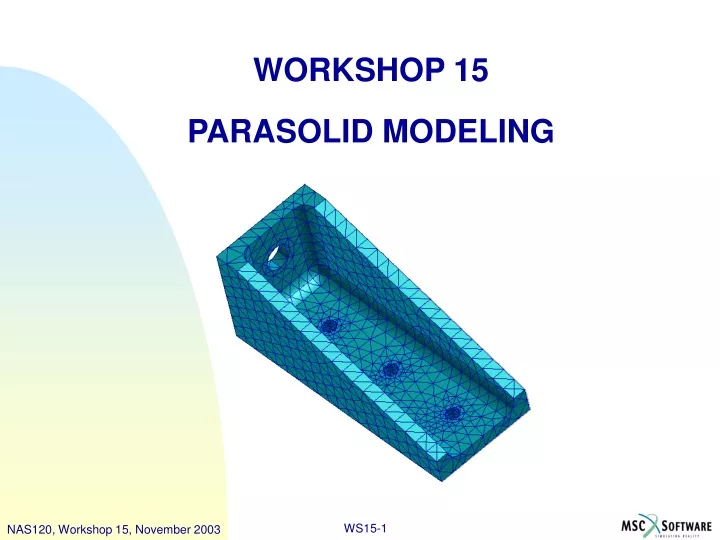
WORKSHOP 15PARASOLID MODELING WS15-1 NAS120, Workshop 15, November 2003
Problem Description • Create a parasolid model of a tension fitting using a number of the parasolid tools in MSC.Patran
Suggested Exercise Steps • Create a new database for the tension fitting model. • Create all the necessary 2D Geometry. • Extrude the surface to begin creating the solid model. • Create a solid shell by removing part of the solid. • Create fillets for all inside edges of the solid. • Create holes for the model by creating solid cylinders that pass through it, and then use boolean to subtract the cylinders. • Create cylinders to imprint the model. • Imprint the solid using the cylinders. • Delete the cylinders used for imprinting. • TetMesh the completed solid • Create loads and constraints on the model that will be used in the analysis. • Create material properties for the model. • Create the 3D element properties. • Check to see that the load case Default has the load and constraint. • Run the analysis by sending the model to MSC.Nastran. • Access the results by attaching the XDB file. • Post-process the results from MSC Nastran.
Step 1. Create New Database for Tension Fitting a b c d e f g • Create a new database called • tension_fitting.db. • a. File / New. • b. Enter tension_fitting as the • file name. • c. Click OK. • d. Choose Tolerance Based on • Model. • e. Select MSC.Nastran as the Analysis Code. • f. Select Structural as the Analysis Type. • g. Click OK.
Step 2. Create Surface a b c d • Create the Geometry for the tension • fitting. • a. Geometry : Create / Surface / • XYZ. • b. Enter <5 2 0> for Vector • Coordinates List. • c. Enter [0 0 0] for Origin • Coordinates List. • d. Click Apply.
Step 2. Create Surface (Cont.) a b c f e h d g • Copy points at opposite corners. • a. Click increase Point Size icon • to show all points enlarged. • b. Geometry : Transform / Point / • Translate. • c. Enter <0.5 0 0> for • Translation Vector. • d. Click in the Point List box. • e. Click on the top-left corner. • f. Enter <0 0.5 0> for • Translation Vector. • g. Click in the Point List box. • h. Click on the bottom-right • corner.
Step 2. Create Surface (Cont.) a b b • Create a curve by connecting the • two translated points. • a. Geometry : Create / Curve / • Point. • b. Click on one of the two • translated points as the • starting point and the other • as the ending point.
Step 2. Create Surface (Cont.) a b c d • Break the surface with the sloped • curve. • a. Geometry : Edit / Surface / • Break. • b. Select the rectangular • surface for the Surface • List and the sloped curve • for the Break Curve List. • c. Click Yes when message • box appears. • d. Click the Refresh • Graphics icon.
Step 2. Create Surface (Cont.) a b c • Delete the upper surface • (above the break curve). • a. Geometry : Delete / • Surface. • b. Click on the triangular • surface for the • Surface List. • c. Click Apply.
Step 3. Extrude the Surface to Create Solid a b c d e f • Create a parasolid solid • by extruding the surface • in the z-direction. • a. Geometry : Create • / Solid / Extrude. • b. Make sure • TetMeshable solid • icon is selected. • c. Enter <0 0 2> for • the Translation • Vector. • d. Click in the • surface list box • and then click on • the surface. • e. Click Iso1 view. • f. Click the Smooth- • shaded icon.
Step 4. Create a solid shell a b d c c • Edit the solid using the shell • method to create a shelled • solid. • a. Geometry : Edit / • Solid / Shell • b. Enter 0.25 for • Thickness and turn off • Auto Execute. • c. Click on Solid Face • List and hold down • the shift key and • select the top, sloped, • and front faces of the • solid. • d. Click Apply.
Step 5. Create Fillets a b c d f e e • Create the fillets on the inner • edges of the solid. • a. Geometry : Edit / Solid / • Edge Blend. • b. Make sure that the constant • radius icon is selected. • c. Enter 0.25 for Constant • Radius. • d. Make sure Edges of Solid • icon is selected. • e. Click on Solid Edge List • and screen pick the two • edges on the inside bottom • of the solid. • f. Screen pick the inside rear • edge of the solid, as shown. • (Patran will automatically • blend the two remaining • inner edges.) It may be necessary to rotate the object in order to see then inner edges more easily. This can be done by holding the middle mouse button and moving the mouse.
Step 6. Create Holes for the Tension Fitting a b c d e f g h i • Create the holes for the tension • fitting by creating primitive solids • that pass through the solid, then • subtracting them. • a. Geometry : Create / Solid / • Primitive. • b. Select the cylinder icon • c. Enter 2.0 for the Height and • 0.25 for the radius. • d. Enter [-1 1.25 1] for the Base • Center Point List and Coord • 0.1 for the Axis List. • e. Click Apply. • f. Geometry : Edit / Solid / • Boolean. • g. Select Subtract icon. • h. Select the tension fitting for • the Target Solid. • i. Select the cylinder for the • Subtracting Solid List.
Step 6. Create Holes for the Tension Fitting (Cont.) a b c d h i e f g j • Create the points where the three • bottom holes will be placed by • translating an existing point and, • then translating again. • a. Click wireframe icon. • b. Geometry : Create / • Point / Extract. • c. Select the Curve Icon. • d. Click in the curve list box • and select the curve as • shown. • e. Geometry: Transform / • Point / Translate. • f. Enter <-0.75 0.25 0> for • Translation Vector. • g. Click in the point list box • and select the new point. • h. Enter <-1.50 0 0> for • Translation Vector. • i. Enter 2 for repeat count. • j. Select the translated point.
Step 6. Create Holes for the Tension Fitting (Cont.) a b c e f h i j j l k d g • Create cylinders using points as base • centers and then create holes by • subtracting them from the solid. • a. Geometry : Create / Solid / • Primitive. • b. Select cylinder icon. • c. Enter -1.0 for Height List • and 0.125 for Radius List. • d. Turn off Auto Execute. • e. Shift-click to select the three • translated points for Base • Center Point List. • f. Enter Coord 0.2 for axis list • and click Apply. • g. Click Smooth Shaded icon. • h. Geometry : Edit / Solid / • Boolean. • i. Select subtract icon and turn off • Auto Execute. • j. Select tension fitting as Target • Solid. • k. Shift-click all three cylinders for • Subtracting Solid List. • l. Click Apply. It may be necessary to rotate the object several times in order to select the cylinders with ease
Step 7. Create Cylinder to Imprint Tension Fitting a b c d e f g h i j c g • Create a point in the center of the • large hole in order to create a • cylinder to imprint onto the solid. • Then create the cylinder that will be • used for imprinting. • a. Click wireframe icon. • b. Geometry : Create / Point / • ArcCenter. • c. Select the hole edge. • d. Geometry : Create / Solid / • Primitive. • e. Select cylinder icon • f. Enter 1.0 for Height and • 0.371 for Radius. • g. Click on point in the center of • the big hole. • h. Enter Coord 0.1 for Axis List. • i. Click Apply. • j. Click Smooth Shaded icon.
Step 8. Imprint the Solid a c b • Use the cylinder to imprint the • solid and then delete the • cylinder, resulting in the • finished solid. • a. Geometry : Edit / Solid / • Imprint. • b. Select the tension fitting • for the Solid List (A). • c. Select the cylinder • for the Solid to Imprint • List (B). The solid may seem unchanged, but the imprint on the solid will not be visible until the the cylinder has been deleted.
Step 9. Delete the Cylinders a b c • Delete the cylinder and make sure • imprint method was completed. • a. Geometry : Delete / Solid • b. Select the cylinder for • Solid List. • c. Click Apply.
Step 10. TetMesh the Completed Solid a b c d e • Create the TetMesh for the • tension fitting. • a. Elements : Create / • Mesh / Solid. • b. Make sure Tet, • TetMesh, and Tet10 • are all selected. • c. Click on Input List and • select the solid. • d. Remove check for • Automatic Calculation • and enter 0.25 for • Global Edge Length. • e. Click Apply.
Step 11. Create Loads and Constraints a b c d e f g h i g • Create the loads and constraints for • the model. • Click Refresh Graphics icon • Loads/BCs : Create / Total Load / Element Uniform. • Enter Force as the New Set Name. • Click Input Data… • Enter <-5000 0 0> for the Load and click OK. • Click Select Application Region… • Select the annular face created by imprinting at the larger hole, then click Add. • Click OK • Click Apply. Illustrated here is the desired application region.
Step 11. Create Loads and Constraints (Cont.) a b c d e f g h i j h • Create the constraints on the base holes. • a. Loads/BCs : Create / • Displacement / Nodal. • b. Enter Fixed as New Set Name. • c. Click Input Data… • d. Enter <0 0 0> for Translation • only, and click OK. • e. Click Select Application Region. • f. Click on Select Geometry Entities. • g. Select Surface or Face icon • h. Shift-click the cylindrical surfaces at • the three holes on the base, and • Click Add. • i. Click OK. • j. Click Apply. Illustrated here is the desired application region for one of the three holes.
Step 12. Create Material Properties a b d c e f • Create the material properties for the • model. • a. Materials : Create / Isotropic / • Manual Input • b. Enter Aluminum for Material • Name. • c. Click Input Properties… • d. Enter 10E6 for Elastic • Modulus and 0.3 for the • Poisson Ratio. • e. Click OK • f. Click Apply.
Step 13. Create 3D Element Properties a b c d f g e h • Create the 3D element properties for the tension fitting. • a. Properties : Create / 3D / • Solid. • b. Enter 3D_tets for Property • Set Name. • c. Click Input Properties… • d. Click on the Select Material • Icon. • e. Select Aluminum. • f. Click OK • g. Select the solid for • Application Region, and click • Add. • h. Click Apply.
Step 14. Check the Load Case a b c d • Check the load case Default to make • sure that the load and constraint are • selected. • a. Load Cases : Modify • b. Click on the load case name • Default. • c. Check to see that both the • load and constraints are • assigned. • d. Click Cancel.
Step 15. Run the Analysis a b c d e f g h • Run the Analysis with MSC.Nastran. • a. Analysis : Analyze / Entire • Model / Full Run. • b. Click Translation • Parameters... • c. Make sure both XDB and • Print are selected for Data • Output. • d. Click OK. • e. Click Solution Type… • f. Make sure LINEAR STATIC • is selected. • g. Click OK. • h. Click Apply.
Step 16. Access the Results a b c d • Attach the XDB file to access the • results. • a. Analysis : Access Results / • Attach XDB / Result Entities. • b. Click Select Results File… • c. Select tension_fitting.xdb • and click OK. • d. Click Apply.
Step 17. Display Results a b c • Create a deformation plot • a. Results : Create / • Deformation. • b. Select Displacements, • Transitional from • Select Deformation • Result. • c. Click Apply.
Step 17. Display Results (Cont.) a b c d e g f • Erase the geometry and do not show • the undeformed model, so that • only the deformed model is shown. • a. Display : Plot/Erase… • b. Click Erase under Geometry. • c. Click OK. • d. Click Display Attributes. • e. Remove check from Show • Undeformed. • f. For the Render Style, choose • Shaded. • g. Click Apply.
Step 17. Read Results (Cont.) a b c d • Plot the von Mises • stress for the model. • a. Results : Create / • Fringe. • b. Select Stress • Tensor from • Select Fringe • Result. • c. Select Display • Attributes, then set • Display to Element • Edges • d. Click Apply. It may also be helpful to change the view several times in order to get a better visualization of the deformations. This can be done either by holding down the middle button on the mouse, or using the view icons.