Download
1 / 43
450 likes | 1.03k Views
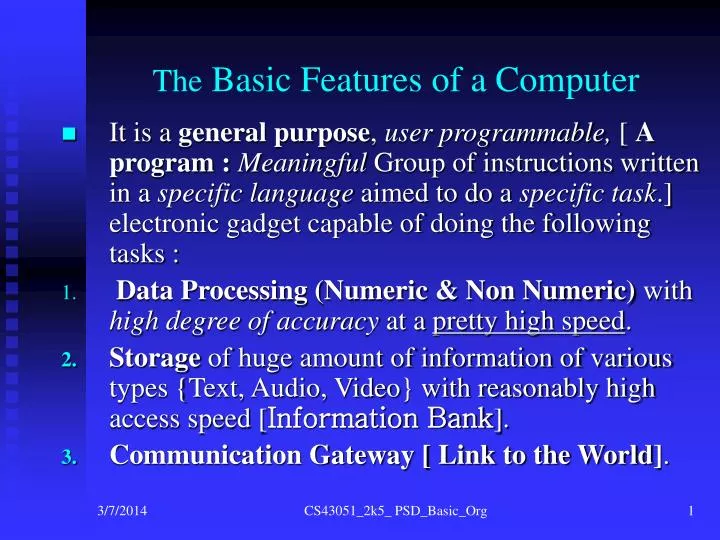
The Basic Features of a Computer It is a general purpose , user programmable, [ A program : Meaningful Group of instructions written in a specific language aimed to do a specific task .] electronic gadget capable of doing the following tasks :

E N D
The Basic Features of a Computer • It is a general purpose, user programmable, [ A program :Meaningful Group of instructions written in a specific language aimed to do a specific task.] electronic gadget capable of doing the following tasks : • Data Processing (Numeric & Non Numeric) with high degree of accuracy at a pretty high speed. • Storage of huge amount of information of various types {Text, Audio, Video} with reasonably high access speed [Information Bank]. • Communication Gateway [ Link to the World]. CS43051_2k5_ PSD_Basic_Org
Computer Vs. Other Electronic Gadgets • Full User programmability : Under some support environment. Like do not divide if the divisor is 0can be achieved through programming in a computer but such a thing cannot be achieved in a calculator /organizer. • Wide ConnectivityOptions: To other computers and various types of peripherals. • Ease of upgradeability: By installing new packages , connecting state of the art peripherals, enhancing memory etc. • Downward Compatibility : Even after several phases of up-gradation, almost all computer systems do provide support for several old versions of Hardware as well as software . This enables investments made at any stage of a computer system useful and effective for many years to come. CS43051_2k5_ PSD_Basic_Org
Data Processing Activity of any Typical Computer (achieved by executing some program) • Numeric Operations involving manipulation of Integers and Floating Point Numbers that includes very large values too (achieved throughSpecial Application Programs) . • Logical Operations like comparing two items. 3.Non Numeric Operations that includes among all things the following : 4a) Arranging Data Items like preparation of merit list. 4b) Manipulating Pictures & Graphics. 4c) Multimedia applications ( Audio, Video, Graphics, Video) 4d) Create, format, send & receive messages of various forms. CS43051_2k5_ PSD_Basic_Org
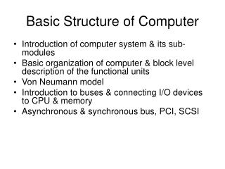
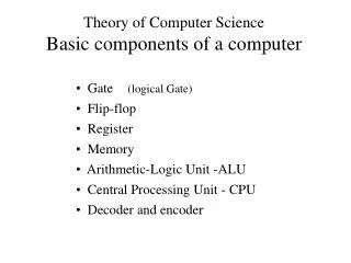
Computer Components – 1 [ C.P.U. ] Each & every computer MUST carry out some form of processing , hence it must possess : • A Processing Element / Processing Unit / Processor {Arithmetic, Logical, Manipulation of Messages}. • The processing tools i.e. the instructions available for processing . These instructions constitute any program framed to accomplish any kind of processing. • Ability to properly sequence the processing steps / instructions to achieve the desired result { Control}. The above three are closely linked together hence can all be encapsulated into the C.P.U. { Central Processing Unit}. CS43051_2k5_ PSD_Basic_Org
The Components of the C.P.U. • Arithmetic & Logical Processing Unit [ The A.L.U]. • Associated Data Storage Components / Scratch Pad Storage. Electronic Storage (The Registers). • The implementation of the Instruction Set as well as the unit that controls & sequences all operations in accordance with the supported Instruction Set [ The Control Unit ] . • The interface with other components of a Computer ( To be illustrated in due course ). CS43051_2k5_ PSD_Basic_Org
The CPU Components Register ALU Control Unit CS43051_2k5_ PSD_Basic_Org
Computer Components – 2 [ The Memory ] • Memory : Essential to create any form of Information Bank/ Data Repository. Wide range & types of Memory & Storage Media are available/ in use now –a –days . CS43051_2k5_ PSD_Basic_Org
Generalized Memory Structure • Large Data Storage repository. • Structure is NOT dictated by what is stored in that memory (Content Independent). • Several access mechanism modes exists to access it’s content . • Any memory can be thought to be composed of several individually addressable blocks each of which contains some data item(s). CS43051_2k5_ PSD_Basic_Org
User Requirement/ Ideal View point of the Computer Memory • Should be Infinite Sized. • Should possess High Speed of access. • Should be of Low Cost . • Has to be Reliable. • Must be Expandable with little or no affect on the existing system configuration. • Must be flexible & adaptable to change in size as well as to compatibility with new emerging technologies. CS43051_2k5_ PSD_Basic_Org
Classification of Memory Classification A ( Media Types). • Electronic [ ROM, EPROM, Static RAM, Dynamic RAM, Flash , Memory Stick]. • Magnetic [ Hard Disk, Flex Disk, Tape, DAT]. • Optical [CD-R/ -RW, DVD-R/RW, DVD-RAM]. Classification B ( Data Retention Property). • Volatile. [ Electronic ] • Non Volatile. [ Flash, Magnetic , Optical]. Classification C ( Alterability Property). • User Alterable.[ RAM, Flash, Disk, Tape, DAT, CD-RW, DVD-RW] • Non Alterable [ROM, EPROM, CD, DVD]. Classification D ( CPU Proximity & Accessibility, Most System Relevant). • Register. {Electronic, Volatile, User Alterable}. • Cache.{Electronic, Volatile, Transparent to User} • Main / Primary. {Electronic, Volatile, User Alterable}. • Secondary . {Flash, Magnetic Disks & Tapes, Optical, Non Volatile, Some User Alterable}. CS43051_2k5_ PSD_Basic_Org
The Typical Memory Hierarchy Electronic Mostly Volatile GPRs SIZE COST & SPEED On Chip CACHE Off Chip Cache Main/ Primary / Physical Memory Fixed Secondary Memory [ Magnetic Disk ] Non Volatile Removable Secondary [ Mag.Tapes, Electronic Flash, Optical CD_ROM, DVDs] Non Volatile CS43051_2k5_ PSD_Basic_Org
System Programmers’ view point of the Computer Memory • The actual Physical Memory is finite sized like a large , fixed size , one dimensional column vector. • Any user should not be affected by the available / existing memory capacity. Any one user process’s space requirement may exceed the total available / existing memory capacity but still can be run in the system with no marked degradation in response time / performance. • There will be more than one user process together with the operating system resident in the existing memory at any point of time. • The existing memory capacity, if enhanced , will not force a regeneration of the system but rather will improve response time.
The Actual Memory Levels( Look Through Configuration ] CPU COST & SPEED On Chip MMU SIZE Cache [ On Chip + Off Chip ] Each Hierarchical Level represents a Higher Speed Version that contains some portion of its immediate Next Hierarchical Level Cache _ Main Interface Main / Physical Memory Secondary Memory + Associated Interface CS43051_2k5_ PSD_Basic_Org
The Memory Hierarchy • MMU : Memory Management Unit acts as the interface [interconnection block] between the CPU and the Memory System.It helps to manage the finite sized main memory in such a way that it appears to the user as an Infinite Sized High Speed Memory. • Cache Memory : A high speed partly content addressable memory which represents a high speed window of the Main Memory. Its typical size happens to be 256 KB. CPU normally accesses the Main Memory through the Cache Memory (look through configuration). It does not add up to the main memory space in any way.We shall however initially assume that this Cache Memory is transparent till it is formally introduced later. CS43051_2k5_ PSD_Basic_Org
Basic Read Write Memory (RWM) Organization Data In WRITE Input Buffer S E L E C T I O N Addressable Unit / Block #1 ADDRESS IN DATA BUS Addressable Unit / Block #i Addressable Unit / Block #N OUT DATA BUS READ Output Buffer Data Out CS43051_2k5_ PSD_Basic_Org
Features of an Electronic Memory CS43051_2k5_ PSD_Basic_Org
An Electronic Memory Location & Its Content • Memory is shown here as a group of Mail Boxes actually a group of 8 (Eight)electronic storage cellsaddressable together. • Each byte can assume one of 256 different values since using 8 bits one can represent 2 8 = 256 different values. • Each location has a unique numeric identifier which denotes its address. Note the addresses shown in the previous slide e.g. box. No. 0 , 1, 2 etc. • Each address can hold any one of 256 possible values as data as has been depicted. CS43051_2k5_ PSD_Basic_Org
An Electronic Memory Location (an Inside View) • Each Location of any Electronic Memory (usually one byte / 8 Bits) can be viewed as a parallel –in – parallel-out (PIPO) Register composed of 8 no. of D F/Fs. • The Addressing Mechanism is implemented using Address Decoder. • The Data Read Signal is actually achieved through Output Enable (OE) signal . • The Data Write Signal represents the Write Clock / the Clock of the D F/Fs (all tied together) . CS43051_2k5_ PSD_Basic_Org
Byte Organized Memory Vs. Multi Byte CPU • Main Memory is byte organized (normally). • Modern day CPUs can handle multi byte words (usually integral multiples) say 4 bytes. • In such a case one of the two following storage pattern is followed : 1) Little Endian : Lower Memory Address holds lower order byte.[ Intel Convention ]. 2) Big Endian : Lower Memory Address holds Higher Order byte. CS43051_2k5_ PSD_Basic_Org
Storage Pattern of n X 8 bit ( n an integer) Data, in Byte Organized Memory Example : n = 4 i.e. 32 bit Data 32 bit Data Word : A2 24 3C 4B [ 8 Hex Digits ] 4 byte Memory Block starting from A000 0000 (32 bit Address) Address Content in Hex in Hex (Little Endian) ( Big Endian ) ---------------------------------------------------------------------- A000 0000 4B A2 ---------------------------------------------------------------------- A000 0001 3C 2 4 ---------------------------------------------------------------------- A000 0002 24 3C ---------------------------------------------------------------------- A000 0003 A2 4B ---------------------------------------------------------------------- CS43051_2k5_ PSD_Basic_Org
Input Output Peripherals • Helps to establish link between computer / cyber world & Real World. Various forms of I/O Peripherals exists. • Common Input Peripherals : Key board, Mouse. • Common Output Peripherals : Video Monitor, Printer. CS43051_2k5_ PSD_Basic_Org
Peripheral Interfaces - 1 • Most of the peripheral devices helps in establishing human interface to the computer System (mainly CPU & Memory). • Each of the peripheral differs in characteristics from each other as well as from the electronic parts (CPU & Memory) in terms of electrical features and operating speed. • Some kind of programs are required to control all the various peripherals (Device Drivers) . • Users interact with any computer either by some command or alternately by mouse click . Hence some form of command interpreter or Graphic User interface [GUI] is needed . • These device driver programs as well as Command Interpreter & GUI forms part of the existing Operating System . CS43051_2k5_ PSD_Basic_Org
Peripheral Interfaces - 2 • All peripherals must possess the following things : a) An Electronic Peripheral Interface that helps to isolate the CPU & Main Memory from the diverse world of peripherals. b) CPU – Peripheral connectivity is established through the following components : 1) Electronically addressable Command Register (Write Only). 2) Electronically addressable Status Register (Read Only). 3) Electronically addressable Local Data Buffer (Read/Write). CS43051_2k5_ PSD_Basic_Org
BUS : The Connection Gateway • Group of Electrical Lines ( cables and/or PCB Tracks OR both ) performs a particular task in unition. • Helps to connect the Different Components of any Computer System. CS43051_2k5_ PSD_Basic_Org
CPU – External World Connectivity - 1 1) CPU must be able to address each device interface as well as each memory location. This Address is sent via a group of electrical lines / PCB Tracks termed as the Address bus. 2) CPU sends / receives datato / from the device interface & memory through a separate group of lines termed as Data Bus. 3) CPU sendsCommand to / or reads Device Status from the device interface / memory via a 3rd group of lines known as the Control Bus. CS43051_2k5_ PSD_Basic_Org
The Different Buses Address Bus - Group of lines that is used to carry address information from the CPU to the concerned device(s). Address is one that helps the CPU to select one among many devices. Hence it is unidirectional. Data Bus - The group of lines used to carry data/information from the device to CPU &vice versa. It is always bi-directional. Control Bus – The group of lines that enables the CPU to control various activities by sendingappropriate commands as well as monitor status of the concerned device e.g. Read Signal, Write Signal,Status Set Signal. Each bus consists of a number of lines, which is represented in a compact manner. Bi Directional Bus composed of 32 Lines 32 CS43051_2k5_ PSD_Basic_Org
Memory Bus & I/O Bus • As has already been mentioned , Peripherals presents a much larger diverse interface scenario than the Memory. • The entire Memory hierarchy interacts with the CPU through some pre-specified protocol. • Whereas, large diverse nature of Peripheral Interfaces demands a much larger variety of interface protocols . • This demands different set of Buses , namely, I/O Bus and Memory Bus to connect peripherals and Memory respectively with the CPU. • However, any type of BUS, in principle , must essentially compose of ADDRESS, DATA & CONTROL Buses only differing in signal level & layout. CS43051_2k5_ PSD_Basic_Org
Typical Bus Level Organization CS43051_2k5_ PSD_Basic_Org
Typical WRITE Sequence CPU Storing Data to a Memory Location/ Sending Data / Command to Device Interface Register(s) Say CPU wants to Write Decimal Value 11 into location / address 2 (Decimal) . • CPU sends (floats) 2 via its Address Bus. This value 2 coming via address bus will select the Memory Location/ Device Interface Buffer location whose address happens to be 2 (Decimal). • CPU next sends value 11 via its Data Bus . The CPU also asserts the Write Signalthrough itscontrol busat the same time. This Write Signal will write11 (value sent via data bus) in the location already selected by the address bus (2 here). • CPU waits for the Acknowledgement signal via its Control Bus, from the written place before proceeding with the next write. (necessary for slow devices)
Typical READ / FETCH Sequence CPU Loading Data from Memory / Device Interface Registers OR Fetching Instruction from Memory Say CPU wants to Read from the location whose address happens to be 3 (Decimal) or 0000 0000 0000 0011 in 16 bit Binary. • CPU sends (floats) 3 via its Address Bus. This value 3 coming via address bus will select the Memory Location/ Device Buffer Location whose address happens to be 3. • The CPU also asserts the Read Signalthrough itsControl Busat the same time. This Read Signal will read i.e. make available on the data bus the value/ data content of the location already selected by the address bus (3 here). • CPU next waits for the READY signal sent through its Control Bus from the concerned Memory Location/ Device interface buffer (a must for slow device) before probing its Data Bus and then it must store the data existing on the Data Bus (READ from the location 3 ) into a relevant storage place lying inside it[ CPU’s local memory store ]. This local memory store inside any CPU is termed as REGISTER. Several Registers may exist inside any CPU. Some of them are special purpose while others are general purpose registers [GPRs] .
Computer Architecture & Operating System • Architecture : Functions of the different hardware / organizational blocks of a Computer System. - CPU. - Memory ( Main & Secondary). - Input & Output Peripherals. • Operating System : A System Software that helps all type of users to operate a computer System. CS43051_2k5_ PSD_Basic_Org
The Functions of the CPU • The CPU (Central Processing Unit) performs the following tasks by executing Instructions of some specific program stored in Main Memory. 1) Controlling all peripheral devices. [ Relevant Device Driver Program(s)]. 2) Communicating with all types of Remote Devices. [ Network Protocol Program ] 3) Recognizing user commands [ Operating System (O.S.) ]. 4) Inputting Data [ Device Driver invoked by the O.S.]. 5) Producing Output (on screen /or on printer) after obtaining Data from Main/Secondary Memory.[Device Driver thro O.S.] 5) Performing arithmetic & logical operations.[ As per Specified Instruction(s) of the executing program]
The CPU Performance Parameters - 1 N.B: All the activities of any CPU are being carried out by executing some machine level /low level instruction. 1. CPU Speed : Each instruction takes a definite time to complete execution. This time is measured in terms of the Number of CPU Clock Periods needed to execute that instruction ( The Instruction Latency). Hence one way to measure the CPU speed is Number of Instructions executed / second (termed as the Throughput) . Typical unit isMIPS (Millions of Instructions per second) or MFLOPS (Millions of Floating point Operations performed per second.)However one normally finds the CPU Clock frequency as rough estimate of its speed i.e. higher the clock frequency higher will be the CPU speed. But in actual terms speed will be affected depending on the most frequently used instructions hence the Throughputhappens to be a more fair estimate of the CPU speed estimated by executing some benchmark programs . CS43051_2k5_ PSD_Basic_Org
The CPU Performance Parameters - 2 2. CPU Processing Power : The Operand Size (in bits) it can handle at one go i.e. in a single machine instruction normally. This is directly related to its ALU ( Arithmetic Logic Unit a purely combinational Circuit) width. e.g. Pentium is a 32 Bit CPU Any Machine level instruction of a Pentium Processor can handle 32 bit operands or Pentium contains 32 bit Integer ALUs. N.B: This Operand Sized based classification is interesting in the sense that any n bit CPU can also be used to handle larger sized data provided one writes proper programs to achieve that which gets translated into n bit processing instructions by the Translator Program (The Compiler). CS43051_2k5_ PSD_Basic_Org
The Functions of Electronic Physical Memory - 1 • Acts as the brain of the Computer System. Functions as the only accessible storage for the CPU i.e. anything & everything MUST first be brought in the Physical Memory before it can be accessed by the CPU. • Stores inputted commands, data, program as well as intermediate & final results. • CPU stores data into it and retrieves data as well as Instructions from it . • It is composed of several locations , each location size is normally one byte or its integer multiple . (1 byte = 8 Bits = 1 Character). • It is finite sized ( typical capacity 512 Mbytes(MB) ), Electronic , Volatile and Random Access [Time taken to access any location is identical ] and relatively costly.
The Functions of Electronic Physical Memory - 2 6. The main memory can be viewed as a very large sized , one dimensional matrix /array, a column vector. Time taken to access any element/location happens to be the same . 7. Some part of it is non volatile (Read Only Memory [ROM] ) some of it is Read Write Memory [RWM] commonly termed as RAM (Random Access Memory). • Now a days slow Dynamic Main Memory is connected to the CPU through a high speed electronic Memory known as the Cache Memory as well as the Memory Management Unit (MMU). • The Cache as well as the MMU helps to interface the higher word sized, high speed CPU with the byte wide, low speed Main Memory.
The Secondary Memory Functions (Input{Load}+Output {Store}) • Acts as the Back up Store of the Computer System. • Can be viewed as a Filing Cabinet for storing Data , Program by the CPU { Backbone of the File System in any computer}. • It represents the Non Volatile form of storage. • As compared to main memory the secondary memory represents slow, Large Capacity ( Theoretically infinite { Helps in building Virtual Memory}) , relatively cheap medias like the following : • Magnetic Medias like Fixed / Winchester [Hard] Disks or Removable Media like Floppy,Tape , DAT etc • Removable Optical Medias like CD /DVD– ROMs ( Read only) , CD/DVD-R (Recordable in a place once only ), CD/DVD-RW (Rewritables) • Removable Electronic Non Volatile Compact Memory like Memory Sticks, Pen Drives [ Flash Memory] . • It represents infinite capacity storage because of the existence of removable media components.
Peripheral & Remote Devices Peripherals/ Peripheral Devices : All those Devices that lie in the Periphery of the CPU. All Peripheral Devices are connected to the CPU through several Buses (as illustrated earlier) and are controlled by the CPU through some Device Driver program (s). Remote Devices : Those which are far away from the current CPU/ Computer System connected through the Network Interface. CS43051_2k5_ PSD_Basic_Org
Input Peripheral Devices and their Functions ( Architectural Aspects) • These are employed to feed data , program, picture, commands to the Computer System. A few commonly used devices are the following : • Keyboard ( The earliest and still most commonly used Input Device).: To type in Commands and/or Data [Alphabets, Digits, Symbols etc.] • The Mouse : Commands are given by clicking its left/right button. It works in a Graphic Environment where user is given option to select among several Options in a menu by moving mouse button on to that item and clicking on that. CS43051_2k5_ PSD_Basic_Org
Output Peripherals and their Functions- 1 • Output Peripherals are responsible for providing some form of response/result to the user. Commonly used Output peripheral devices are : • Visual Display Unit (VDU) Screen / Monitor : Is used to display the following • Anything typed in via keyboard. • The various menus available to the user. • The response generated by the system to various user commands in some way. • The result generated by running various programs/ packages. CS43051_2k5_ PSD_Basic_Org
Output Peripherals and their Functions - 2 2. Printers : Used to produce printed Outputs / Hard Copy. Various types of printers : • Impact Printers : Where there exists a physical printing Mechanism/ print head that strikes on the paper & ink ribbon to make an impression on the Paper. These mostly print in Black . Examples of such printers are Dot Matrix , Line , Band etc. • Non Impact Printers : Here there exists no physical printing heads rather printing is done by electronic/electrostatic mechanism that regulate the flow of ink/toner which are electro statically deposited on the paper. These can print both in Monochrome (black) as well as in Color. Commonly used printers are Inkjet, Desk jet, Laser etc. Graphic Printers like Dot Matrix, Inkjet, Desk Jet, Laser can print both text as well as pictures while Line Printer, Band Printer can only print characters . But these are high speed & rugged compared to graphic printers . CS43051_2k5_ PSD_Basic_Org
The Actual Scenario - 1 • Each & every CPU works by executing some pre-written , stored programs . Some of these programs like Editor, Operating System, Translator( Compiler/Assembler), Linking Loaders [ System Programs] are not written by the ordinary users but are already written and maintained by the System Programmer(s).Other Programs are termed as Application Packages. • These System Programs as well as some application packages are preserved as executable files in the secondary memory / Non Volatile Store. • However , in order to be executed, any executable file will have to be brought into the volatile main memory. • Power on self test Program as well as some of the device driver programs like Keyboard Driver , Display Driver and Disk Read/Write Drivers are needed immediately after power on , hence these needs to be available in some non volatile, unalterable section of the electronic main memory [ROM]. CS43051_2k5_ PSD_Basic_Org
The Actual Scenario - 2 • In order to execute any program CPU has to execute its instructions stored in main memory one by one. • Before execution CPU will have to read/ fetch the instructions inside some of its register from main memory. • Any activity inside the Computer Systemwill have to be initiated by the CPU in accordance with an instruction execution. • Respond to any user command , peripheral control & communications are done by the various modules of the Operating System [ O.S.] program. • The Operating System modules initially starts running and subsequently are invoked from within some user program by system call (via software interrupt) , exceptions OR through device/hardware interrupts. CS43051_2k5_ PSD_Basic_Org