Download
1 / 39
400 likes | 684 Views
Ge 116 Module 2: Electron Probe. Part 1: instrument basics, WDS X-ray analysis and standardization. Electron Probe: Parts. (5 of these). Electron Microprobe Instrumentation. What Makes a Microprobe? High Stability Electron Source Focussing WDS X-ray Optics High Precision Stage

E N D
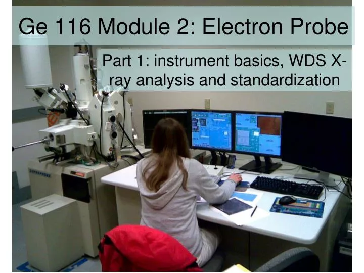
Ge 116 Module 2: Electron Probe Part 1: instrument basics, WDS X-ray analysis and standardization
Electron Probe: Parts (5 of these)
Electron Microprobe Instrumentation • What Makes a Microprobe? • High Stability Electron Source • Focussing WDS X-ray Optics • High Precision Stage • Reflected Light Optics • Beam Current (Faraday Cup)
WDS Spectrometers This is a Cameca spectrometer, but JEOL design is pretty similar Crystals (2 pairs) Proportional Counting Tube (note tubing for gas) PreAmp
Electron Probe: WDS spectrometers • Rowland Circle: crystal moves in straight line away from sample focus point, detector must move along curve to remain on circle • With vertical Rowland circle, can pack lots of spectrometers around machine but X-ray counts very sensitive to Z focus
Pseudocrystals/LSMs Goldstein et al, p. 280
Crystals in our probe • SP1: TAP, PET, LDE1, LDEB • SP2: PET, LIF • SP3: PET-L • SP4: TAP, LDE2 • SP5: PET-H, LIF-H • Example protocol: • SP1 TAP: Na, Mg • SP2 PET: Ca, Ti • SP3 PET-L: K, P • SP4 TAP: Al, Si • SP5 LIF-H: Mn, Fe
Electron Probe: gas proportional counters • With increasing bias, gas counters go from ionization chamber to proportional counting to Geiger cascade region (in proportional region, can use energy of X-ray to suppress counting of wavelength multiples)
Electron Probe: gas proportional counters • Trade-off between window thickness and gas pressure • Gas flow P10 vs. sealed Xe
WDS provides roughly an order of magnitude higher spectral resolution (sharper peaks) compared with EDS. Plotted here are resolutions of the 3 commonly used crystals, with the x-axis being the characteristic energy of detectable elements. Note that for elements that are detectable by two spectrometers (e.g., Y La by TAP and PET, V Ka by PET and LIF), one of the two crystals will have superior resolution. When there is an interfering peak and you want to try to minimize it, this knowledge comes in very handy. Spectral Resolution Reed, 1995, Fig 13.11, in Williams, Goldstein and Newbury (Fiori volume)
PbS BaSO4 Electron Probe: wavelength scans and peaking Al Ka Peaks • WDS has much higher spectral resolution than EDS, which is a big advantage, but peak shifts can be significant, so you have to check peak positions and match your standards well
Bkg under peak High bkg Low bkg Electron Probe: background correction • Can use wavelength scans to find featureless regions near peak for background fitting. • For standard elements, this has already been done; for exotics you have to do it yourself
Quantitative Analysis • Background-corrected on-peak counting rate on standard (composition known), normalized to Faraday cup current: Iistd (counts/sec/nA) • Background-corrected on-peak counting rate on unknown, normalized to Faraday cup current: Iiunk (counts/sec/nA) • Ratio Iiunk/Iistd is called the ‘k-ratio’. To first order it equals the ratio of element concentration in unknown to that in standard.
This plot of Fe Ka X-ray intensity data demonstrates why we must correct for matrix effects. Here 3 Fe alloys show distinct variations. Raw data needs correction
The Fe-Ni alloys plot above the 1:1 line (have apparently higher Fe), because Ni atoms present produce 7.278 keV X-rays, above Fe K edge of 7.111 keV.Thus, additional Fe K are produced by this secondary fluorescence. Absorption and Fluorescence • The Fe-Cr alloys plot below the 1:1 line (have apparently lower Fe), because Fe atoms produce X-rays of 6.404 keV, greater than the Cr K edge of 5.989 keV. Thus, Cr K is increased while Fe K are “used up”.
Z A F In addition to absorption (A) and fluorescence (F), there are two other matrix corrections based upon the atomic number (Z) of the material: one dealing with electron backscattering, the other with electron penetration (or stopping). These deal with corrections to the generation of X-rays. C is composition as wt% element (or elemental fraction).
Unanalyzed elements The matrix corrections assume that all elements present (and interacting with the X-rays) will be included. There are situations, however, where either an element cannot be measured, or not easily, and thus the analyst must make explicit in the quantitative setup the presence of unanalyzed element/s -- and how they are to be input into the correction. Typically oxygen (in silicates) is calculated “by stoichometry” (which requires valence of cations). Elements can also be defined in set amounts, or relative proportions, or “by difference” – although this later method is somewhat dangerous as it assumes that there are no other elements present.
Some remarks on standards EPMA’s claim to fame as a microanalytical tool rests upon (1) faith in a correct matrix correction and (2) use of “good”, “correct”, “true” standards. How do you know whether to trust a standard?
Standards • In practice, we hope we can start out using the “best” standard we have.* There have been 2 schools of thought as to what is the “best” standard is: • a pure element, or oxide, or simple compound, that is pure and whose composition is well defined. Examples would be Si or MgO or ThF4. The emphasis is upon accuracy of the reference composition. • a material that is very close in composition to the unknown specimen being analyzed, e.g. silicate mineral or glass; it should be homogenous and characterized chemically, by some suitable chemical technique (could be by epma using other trusted standards). The emphasis here is upon having a matrix that is similar to the unknown, so that (1) any potential problem with the matrix correction will be minimized, and (2) any specimen specific issues (i.e. element diffusion, volatilization, sub-surface charging) will be similar in both standard and unknown, and largely cancel out. * This is based upon experience, be it from prior probe usage, from a more experienced user, from a book or article, or trial and error (experience comes from making mistakes!) It is commonly a multiple iteration, hopefully not more than 2-3 efforts.
Standards - Optimally • Ideally the standard would be stable under the beam and not be altered (e.g., oxidizable or hygroscopic) by exposure to the atmosphere. • It should be large enough to be easily mounted, and able to be easily polished. • If it is to be distributed widely, there must be a sufficient quantity and it must be homogeneous to some acceptable level. • However, in the real world, these conditions don’t always hold. “Round Robins” On occasion, probe labs will cooperate in “round robin” exchanges of probe standards, where one physical block of materials will be examined by several labs independently, using their own standards (usually there will be some common set of operating conditions specified). The goal is to see if there is agreement as to the compositions of the materials.
Sources for standards : • Purchased as ready-to-go mounts from microscopy supply houses as well as some probe labs ($1200-2000) • Alternately, most probe labs develop their own suite of standards based upon their needs, acquiring standards from: • Minerals and glasses from Smithsonian (free) • Alloys and glasses from NIST (~$100 ea) • Metals and compounds from chemical supply houses (~$20-60 ea) • Specialized materials from researchers (synthesized for experiments, or starting material for experiments) – both at home institution as well as globally (some $, most free) • Swap with other probe labs • Materials from your Department’s collections, local researchers/ experimentalists, local mineral shop or national suppliers (e.g., Wards)
Thoughts on beam current • Is more beam current always better? No. • Detector saturation…too much deadtime • Sample heating (example: Mica at 50 nA, 1 m spot -> 514 °C of heating!) • Element migration (Na diffuses away from beam, especially in hydrous glasses) • Loss of spatial resolution (higher current = bigger beam) T = max temp rise E = accelerating potential in keV I = beam current in A k = thermal conductivity in W/mK d = beam diameter in m
Reducing beam damage • For beam-sensitive samples (like hydrous, high-alkali glass…) • Reduce beam current (trade-off with counts) • Reduce counting time (trade-off with counts) • Defocus or raster beam over area (need homogeneous, clear spots); need to run standards in same geometry • Run sensitive elements in first pass • Examine counts vs. time experiments to see rate of damage; extrapolate to zero time?
Thoughts on temperature stability • Electron microprobes only operate well in very constant temperature rooms • Changing T causes thermal expansion of the diffracting crystals -> peak shifts • Changing T changes pressure in gas-flow proportional counters -> changes counting efficiency • Others?
Some tricks • Normalization • With replicate data, can test which is more reproducible - raw or normalized data • Secondary standards • No physics here, just empirical adjustment for machine performance on a given day
X-ray mapping • Usually done in qualitative mode, that is not background corrected, normalized, or referenced to a standard • Can introduce empirical two-point calibration to semi-quantify maps • Map quality is a function of counting time, mostly
Statistics • Measurement is always a statistical process, and mature understanding of the statistics is essential to proper interpretation of data • There are several ways to look at the precision and sensitivity of electron probe analyses, depending on what question you are asking…
Counting Statistics • X-ray counts are quantized and the number of counts you get in an idealized experiment will always be a Gaussian distribution with standard deviation • Thus, 1% relative precision requires, in theory, 10000 counts. 0.1% relative precision requires 106 counts.
Real Statistics • The real standard deviation of a set of replicate measurements of the same spot is greater than or equal to the ideal value from counting statistics • Longer counting time leads to more instrument drift (source, column, stage, detector, etc.) • In practice, for a well-maintained instrument, if counting time ≤100 s then actual standard deviation Sc ~ 2sc
Real Statistics • Furthermore, quantification requires background correction • Hence, the estimated peak counting rate P is really based on 3 measurements: (P+B), Blow, Bhigh • These uncertainties add in quadrature and can increase Sc of the estimate (P+B) – B by a large factor if P/B is small
Statistical Tests • 1. Sample homogeneity • Based on multiple point analyses or mapping, is a phase homogeneous at some level of confidence? • 2. Analytical Sensitivity • For (repeated?) measurements of two different concentrations, how different must they be before they can be distinguished at some level of confidence? • 3. Detection Limit • What concentration of a trace element is necessary before its presence in a sample can be established at some level of confidence?
Statistical Tests • 1. Sample homogeneity • Approximate formula: 99% confidence corresponds roughly to all n analyses falling within a range • So for 105 counts per point at C = 10%, W~0.1%. Obviously this can’t be very right since it does not depend on n • Better formula:
Statistical Tests • 2. Analytical Sensitivity • How long should you count each point in a profile in order to get a smooth profile? • For a gradient from 5% to 4% over 25 mm, a profile of 25 points at 1 mm steps needs DC ≤ 0.04% to appear smooth, and this takes ≥85000 counts per step • The same gradient with 10 points at 2.5 mm spacing needs DC ≤ 0.1% to appear smooth, and this takes only ≥13600 counts per step -> not 2.5x but 15.6x faster!
Statistical Tests 3. Detection Limit