Download
1 / 35
350 likes | 817 Views
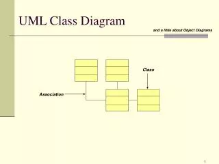
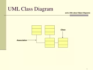
COMPONENT DIAGRAM in UML 2.0 Veronica Carrega. PLAN OF TALK. Introduction about components Components and component diagrams in uml 2.0 Case study Elements of the component Component view: black-box view and white-box view Deployment diagrams. INTRODUCTION.

E N D
PLAN OF TALK • Introduction about components • Components and component diagrams in uml 2.0 • Case study • Elements of the component • Component view: black-box view and white-box view • Deployment diagrams
INTRODUCTION • UML component diagrams describe software components and their dependencies to each others • A component is an autonomous unit within a system • The components can be used to define software systems of arbitrary size and complexity • UML component diagrams enable to model the high-level software components, and the interfaces to those components • Important for component-based development (CBD) • Component and subsystems can be flexibly REUSED and REPLACED • A dependency exists between two elements if changes to the definition of one element may cause changes to the other • Component Diagrams are often referred to as “wiring diagrams” • The wiring of components can be represented on diagrams by means of components and dependencies between them
INTRODUCTION An Uml diagram classification: • Static • Use case diagram, Class diagram • Dynamic • State diagram, Activity diagram, Sequence diagram, Collaboration diagram • Implementation • Component diagram, Deployment diagram UML components diagrams are • Implementation diagrams: describe the different elements required for implementing a system
INTRODUCTION Another classification: • Behavior diagrams • A type of diagram that depicts behavior of a system This includes activity, state machine, and use case diagrams, interaction diagrams • Interaction diagrams • A subset of behavior diagrams which emphasize object interactions. This includes collaboration, activity, sequence diagrams • Structure diagrams • A type of diagram that depicts the elements of a specification that are irrespective of time. This includes class, composite structure, component, deployment UML components diagrams are structurediagrams
COMPONENT in UML 2.0 • Modular unit with well-defined interfaces that is replaceable within its environment • Autonomous unit within a system • Has one or more provided and required interfaces • Its internals are hidden and inaccessible • A component is encapsulated • Its dependencies are designed such that it can be treated as independently as possible
CASE STUDY • Development of an application collecting students’ opinions about courses • A student can • Read • Insert • Update • Make data permanent about the courses in its schedule • A professor can only see statistic elaboration of the data • The student application must be installed in pc client (sw1, sw2) • The manager application must be installed in pc client (in the manager’s office) • There is one or more servers with DataBase and components for courses management
COMPONENT NOTATION • A component is shown as a rectangle with • A keyword <<component>> • Optionally, in the right hand corner a component icon can be displayed • A component icon is a rectangle with two smaller rectangles jutting out from the left-hand side • This symbol is a visual stereotype • The component name • Components can be labelled with a stereotype there are a number of standard stereotypes ex: <<entity>>, <<subsystem>>
Component ELEMENTS • A component can have • Interfaces An interface represents a declaration of a set of operations and obligations • Usage dependencies A usage dependency is relationship which one element requires another element for its full implementation • Ports Port represents an interaction point between a component and its environment • Connectors • Connect two components • Connect the external contract of a component to the internal structure
INTERFACE • A component defines its behaviour in terms of provided and required interfaces • An interface • Is the definition of a collection of one or more operations • Provides only the operations but not the implementation • Implementation is normally provided by a class/ component • In complex systems, the physical implementation is provided by a group of classes rather than a single class
INTERFACE • May be shown using a rectangle symbol with a keyword <<interface>> preceding the name • For displaying the full signature, the interface rectangle can be expanded to show details • Can be • Provided • Required
INTERFACE • A provided interface • Characterize services that the component offers to its environment • Is modeled using a ball, labelled with the name, attached by a solid line to the component • A required interface • Characterize services that the component expects from its environment • Is modeled using a socket, labelled with the name, attached by a solid line to the component • In UML 1.x were modeled using a dashed arrow
INTERFACE • Where two components/classes provide and require the same interface, these two notations may be combined • The ball-and-socket notation hint at that interface in question serves to mediate interactions between the two components • If an interface is shown using the rectangle symbol, we can use an alternative notation, using dependency arrows
INTERFACE • In a system context where there are multiple components that require or provide a particular interface, a notation abstraction can be used that combines by joining the interfaces • A component • Specifies a CONTRACT of the services that it provides to its clients and that it requires from others components in terms of its provided and required interfaces • Can be replaced • The system can be extended
DEPENDENCIES • Components can be connected by usage dependencies • Usage Dependency • A usage dependency is relationship which one element requires another element for its full implementation • Is a dependency in which the client requires the presence of the supplier • Is shown as dashed arrow with a <<use>> keyword • The arrowhead point from the dependent component to the one of which it is dependent
PORT • Specifies a distinct interaction point • Between that component and its environment • Between that component and its internal parts • Is shown as a small square symbol • Ports can be named, and the name is placed near the square symbol • Is associated with the interfaces that specify the nature of the interactions that may occur over a port
PORT • Ports can support unidirectional communication or bi-directional communication • If there are multiple interfaces associated with a port, these interfaces may be listed with the interface icon, separated by a commas
PORT • All interactions of a component with its environment are achieved through a port • The internals are fully isolated from the environment • This allows such a component to be used in any context that satisfies the constraints specified by its ports • Ports are not defined in UML 1.x
An external view (or black box view) shows publicly visible properties and operations EXTERNAL VIEW • A component have an external view and an internal view • An external view of a component is by means of interface symbols sticking out of the component box • The interface can be listed in the compartment of a component box
INTERNAL VIEW • An internal, or white box view of a component is where the realizing classes/components are nested within the component shape • Realization is a relationship between two set of model elements • One represents a specification • The other represent an implementation of the latter
INTERNAL VIEW • The internal class that realize the behavior of a component may be displayed in an additional compartment • Compartments can also be used to display parts, connectors or implementation artifacts • An artifact is the specification of a phisycal piece of information
INTERNAL VIEW • Components can be built recursively
ASSEMBLY • Two kinds of connectors: • Delegation • Assembly • ASSEMBLY CONNECTOR • A connector between 2 components defines that one component provides the services that another component requires • He must only be defined from a required interface to a provided interface • An assembly connector is notated by a “ball-and-socket” connection This notation allows for succint grafical wiring of components
SEMANTICS • The semantics for an assembly connector : • Are that signals travel along an instance of a connector originating in a required port and delivered to a provided port • The interfaces provided and required must be compatible • The interface compatibility between provided and required ports that are connected enables an existing component in a system to be replaced
SEMANTICS • Multiple connections directed from a single required interface to provided interfaces indicates that the instance that will handle the signal will be determined at execution time
DELEGATION • DELEGATION CONNECTOR • Links the external contract of a component to the internal realization • Represents the forwarding of signals • He must only be defined between used interfaces or ports of the same kind
DELEGATION • The target interface must support a signature compatible with a subset of operations of the source interface • A port may delegate to a set of ports on subordinate components • The union of the target interfaces must be signature compatible with the source interface • Semantics: • Is a declaration that behaviour that is available on a component instance is not realized by that component itself, but by another instance that has compatible capabilities • Is used to model the hierarchical decomposition • Message and signal flow will occur between the connected ports
DEPLOYMENT DIAGRAMS • Deployment diagrams • Show the physical relationship between hardware and software in a system • Hardware elements: • Computers (clients, servers) • Embedded processors • Devices (sensors, peripherals) • Are used to show the nodes where software components reside in the run-time system • There is a strong link between components diagrams and deployment diagrams
DEPLOYMENT DIAGRAMS • Deployment diagram • Contains nodes and connections • A node usually represent a piece of hardware in the system • A connection depicts the communication path used by the hardware to communicate • Usually indicates the method such as TCP/IP
DEPLOYMENT DIAGRAMS • Deployment diagrams contain artifact • An artifact • Is the specification of a phisycal piece of information • Ex: source files, binary executable files, table in a database system,…. • An artifact defined by the user represents a concrete element in the physical world
DEPLOYMENT DIAGRAMS • An artifact manifest one or more model elements • A <<manifestation>> is the concrete physical of one or more model elements by an artifact • This model element often is a component • A manifestation is notated as a dashed line with an openarrow-head labeled with the keyword <<manifest>>
REFERENCIES • UML 2.0 Superstructure Specification August 2, 2003 UML 2 SuperstructureFinal Adopted Specification www.omg.org/cgi-bin/doc?ptc/2003-08-02 • The Diagrams of UML 2.0 by Scott W. Ambler, 2003-2004 www.agilemodeling.com/essays/umlDiagrams.htm • UML overview By Mandar Chitnis, Pravin Tiwari, & Lakshmi Ananthamurthy http://www.developer.com/design/article.php/1553851