Download

1 / 31
350 likes | 606 Views
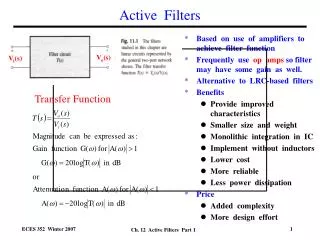
Chapter 11 Filters and Tuned Amplifiers Passive LC Filters Inductorless Filters Active-RC Filters Switched Capacitors. Filter Transmission, Types and Specification. Linear Filters.

E N D
Chapter 11 • Filters and Tuned Amplifiers • Passive LC Filters • Inductorless Filters • Active-RC Filters • Switched Capacitors
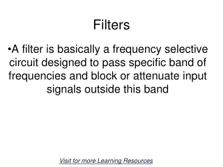
Filter Transmission, Types and Specification Linear Filters
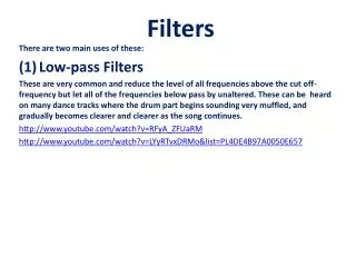
Specification of the transmission characteristics of a low-pass filter. The magnitude response of a filter that just meets specifications is also shown. Filter Specification • Frequency-Selection function • Passing • Stopping • Pass-Band • Low-Pass • High-Pass • Band-Pass • Band-Stop • Band-Reject Summary – Low-pass specs -the passband edge, wp -the maximum allowed variation in passband, Amax -the stopband edge, ws -the minimum required stopband attenuation, Amin Passband ripple Ripple bandwidth
Filter Specification Transmission specifications for a bandpass filter. The magnitude response of a filter that just meets specifications is also shown. Note that this particular filter has a monotonically decreasing transmission in the passband on both sides of the peak frequency.
The Filter Transfer Function Pole-zero pattern for the low-pass filter whose transmission is shown. This filter is of the fifth order (N = 5.)
The Filter Transfer Function Pole-zero pattern for the bandpass filter whose transmission is shown. This filter is of the sixth order (N = 6.)
Butterworth Filters The magnitude response of a Butterworth filter.
Butterworth Filters Magnitude response for Butterworth filters of various order with = 1. Note that as the order increases, the response approaches the ideal brickwall type transmission.
Butterworth Filters Graphical construction for determining the poles of a Butterworth filter of order N. All the poles lie in the left half of the s-plane on a circle of radius 0 = p(1/)1/N, where is the passband deviation parameter : (a) the general case, (b)N = 2, (c)N = 3, (d)N = 4.
Chebyshev Filters Sketches of the transmission characteristics of a representative even- and odd-order Chebyshev filters.
First-Order Filter Functions Fig. 11.14 First-order all-pass filter.
The Second-order LCR Resonator Realization of various second-order filter functions using the LCR resonator of Fig.11.17(b): (a) general structure, (b) LP, (c) HP, (d) BP, (e) notch at 0, (f) general notch, (g) LPN (n0), (h) LPN as s , (i) HPN (n < 0).
The Second-Order Active Filter – Inductor Replacement The Antoniou inductance-simulation circuit. (b) Analysis of the circuit assuming ideal op amps. The order of the analysis steps is indicated by the circled numbers.
The Second-Order Active Filter – Inductor Replacement The Antoniou inductance-simulation circuit. Analysis of the circuit assuming ideal op amps. The order of the analysis steps is indicated by the circled numbers.
The Second-Order Active Filter – Inductor Replacement Realizations for the various second-order filter functions using the op amp-RC resonator of Fig.11.21(b). (a) LP; (b) HP; (c) BP, (d) notch at 0;
The Second-Order Active Filter – Inductor Replacement (e) LPN, n0; (f) HPN, n0; (g) all-pass. The circuits are based on the LCR circuits in Fig.11.18. Design equations are given in Table11.1.
The Second-Order Active Filter – Two-Integrator-Loop Circuit Implementation
The Second-Order Active Filter – Two-Integrator-Loop Circuit Design and Performance
The Second-Order Active Filter – Two-Integrator-Loop Exercise 11.21
The Second-Order Active Filter – Two-Integrator-Loop Derivation of an alternative two-integrator-loop biquad in which all op amps are used in a single-ended fashion. The resulting circuit in (b) is known as the Tow-Thomas biquad.
Fig. 11.26 The Tow-Thomas biquad with feedforward. The transfer function of Eq. (11.68) is realized by feeding the input signal through appropriate components to the inputs of the three op amps. This circuit can realize all special second-order functions. The design equations are given in Table 11.2.
Fig. 11.37 A two-integrator-loop active-RC biquad and its switched-capacitor counterpart.
Fig. 11.47 Obtaining a second-order narrow-band bandpass filter by transforming a first-order low-pass filter. (a) Pole of the first-order filter in the p-plane. (b) Applying the transformation s = p + j0 and adding a complex conjugate pole results in the poles of the second-order bandpass filter. (c) Magnitude response of the firs-order low-pass filter. (d) Magnitude response of the second-order bandpass filter.
Fig. 11.48 Obtaining the poles and the frequency response of a fourth-order stagger-tuned narrow-band bandpass amplifier by transforming a second-order low-pass maximally flat response.