Download
1 / 29
300 likes | 578 Views
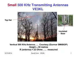
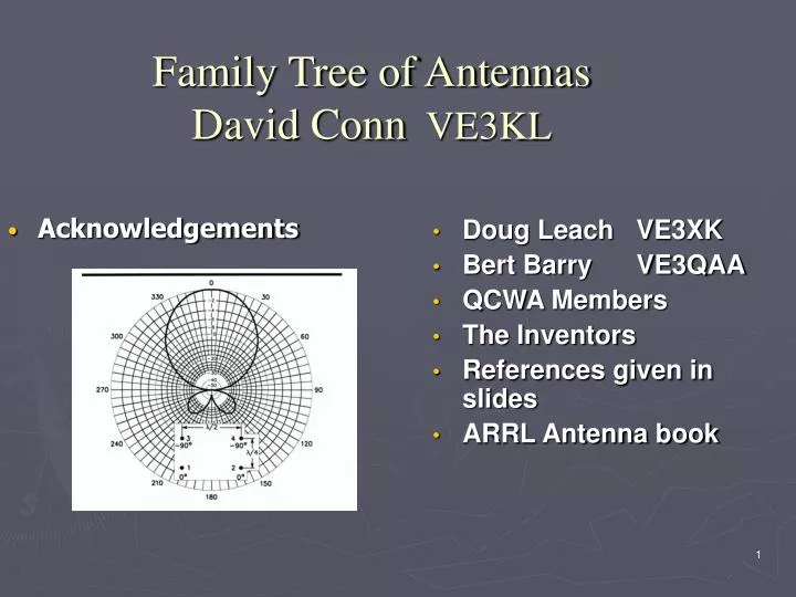
Family Tree of Antennas David Conn VE3KL. Acknowledgements. Doug Leach VE3XK Bert Barry VE3QAA QCWA Members The Inventors References given in slides ARRL Antenna book. Why Make a Family Tree. To understand the overall (complex) picture To enable us to select a good antenna

E N D
Family Tree of AntennasDavid Conn VE3KL Acknowledgements Doug Leach VE3XK Bert Barry VE3QAA QCWA Members The Inventors References given in slides ARRL Antenna book
Why Make a Family Tree • To understand the overall (complex) picture • To enable us to select a good antenna • To organize and compare existing designs Antenna Types
Antenna Types 1…6 • Resonant Wires: Dipole, Yagi, Quad, Vertical, Moxon Square ……. • Long wires (non-resonant): Zepp/G5RV… • Resistively Loaded: Beverage, Pennant, Rhombic … • Small Loops/Wires: Resonant Loading Circuits
Antenna Types 1…6 5. Phased Arrays: Yagi, Collinear, Sterba Curtain, Rhombic, Four Element Rectangular Array, Many Others … • Lens Antennas for UHF/Microwaves: Parabolic Dish, Helix … Family Tree
Radiation Waves Circuits Transmission Lines Ground/Ionosphere Transmitting Antennas Power Receiving Antennas SNR Amateur Radio Antennas (index) Simulation/Smith Chart Microwave UHF/VHF MF HF
Transmitting Antennas • Performance measured by Gain & Directivity • Low Loss: Transmitter Matching • SWR of 2:1 loses half the power • Ground/Ionosphere… dominates • Polarization (Vertical for MF Transmitters)
Receiving Antennas…SNR • Performance measured by RDF (dB) • RDF (Receiving Directivity Factor) defined as peak response in desired direction to average response in all directions • Ground/Ionosphere… extremely important • Consider Polarization: VHF weak signal (DX) uses Horizontal Polarization Antenna Examples
MF AntennasNeed good S/N…not Gain for Receive • Inverted L, T • Beverage Antenna… the best? • Terminated loops (Pennant, Flag) • Vertical Phased Arrays • Vertical GP antennas • K9AY Loop • 4 Square Vertical Green indicates Receive Only Antenna
Inverted L,T,Vertical,K9AY Antennas http://www.antennex.com/preview/archive3/ltv.htm http://www.aytechnologies.com/TechData/LoopInstall.htm
MF Receiving Antenna Performance RDF, dB Vertical phased array B/S 13 2 Broadside Beverages 1.75 W Good Beverage 1.0 W 8.64 Small 4X4 Square Dipole Flag/Pennant K9AY 80 m high Vertical Omni Beverage 0.5 W Bad 5.0 Cost Low Dipole http://www.w8ji.com/antennas.htm
Classic Dipole: type 1 .. Elevation Plot 35 feet Ground RDF = 8.3 dB Good
Classic Vertical Ground Plane: type 1 RDF =5 dB
Two Element Quad…Azimuth: type 1 RDF = 12.84 dB…high 31 feet high to top
MF Pennant…Receive only: type 3 • Ground independent • Very Low Gain (-35 dB) • RDF = 7.39 dB…OK • Cardoid pattern • F/B 25 dB • Small..20 feet each arm • Terminated loop class
Small Magnetic Loop Antenna: type 4Very High Voltages g3ycc.karoo.net/loop.htm
Microwave Antenna Array: type 5 & 6Space Diversity Transmitter Receivers Wanted Rays Unwanted Rays Arrays
Arrays • Driven arrays: Collinear, Sterba and Bobtail Curtains, two dimensional arrays, three dimensional (lens) arrays, Log Periodic • End fire or broadside or any beam shape • Parasitic arrays: Yagi
Four Element Rectangle.. Easy to Visualize ARRL Antenna Book
Collinear Arrays http://www.tpub.com/neets/book10/42i.htm
Bobtail Curtain Driven ArrayMaximum Gain 4.5 dBiLow Angle Radiation ARRL Antenna Book
Log Periodic Antenna Array…looks like a tapered Yagi but each element is driven • Very Broad Band • Dimensions repeat logarithmically • QST Sept. 2002 ARRL Antenna Book
VHF/UHF/Microwave Antennas • Yagi, Quagi, Quads ….stacked versions • Cycloid Dipole… Circular Polarization..Repeaters • Helix and Helix Arrays • Vertical, Jpole • Corner Reflectors, Parabolas, Lenses • Circuit board patch antenna arrays
The J Pole Antenna: type 1 • Easy to Build • No ground plane needed • Many designs available http://www.cebik.com/jp2.html
Cycloid DipoleCircular Polarization…Repeaters: type 1 http://www.wa7x.com/cycloid_info.html
Summary • Tree must include antenna design as well as the physical description • Tree must include: ground effects, basics of the ionosphere • Tree must link to the most important well proven designs • Tree must help amateurs at all levels to select an appropriate antenna
Many Thanks: Especially to the Organizers http://www.dxlc.com/solar/