Download
1 / 26
320 likes | 553 Views
GIS-Assisted Approach in Soil Erosion Assessment using Manifold Software. Introduction. Soil erosion research is a capital-intensive and time-consuming activity. However, the advent of computer technology leads to a new approach in dealing with soil erosion in a watershed.

E N D
GIS-Assisted Approach in Soil Erosion Assessment using Manifold Software
Introduction • Soil erosion research is a capital-intensive and time-consuming activity. • However, the advent of computer technology leads to a new approach in dealing with soil erosion in a watershed. • GIS has the capability of integrating spatial and analytical functionality of spatially distributed data.
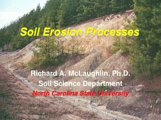
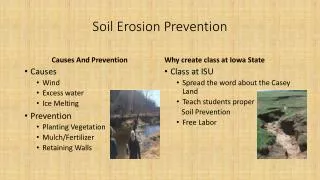
Introduction • Soil Erosion • The removal of soils from their original site • Removes top fertile soil • Source of sediment that pollutes streams and fills reservoirs. • Contributes to non-point source pollution. • Composed of three subprocess (detachment, transport and deposition) • Types of Soil Erosion • Sheet erosion • Rill erosion • Gully erosion • Stream channel erosion
Soil Erosion Models • Universal Soil Loss Equation (USLE) • Empirical model • Estimates soil erosion by raindrop impact and surface runoff • Modifield Soil Loss Equation (MUSLE) • Revised Universal Soil Loss Equation (RUSLE) • WEPP • Rose Erosion Model • CREST • Others
What are the Factors of USLE? • Critical Factors • The critical factors affecting soil erosion were based on the empirical formula developed by Wischmeir and Smith (1978) widely known as USLE. • Erosive power of rainfall (R) • Soil erodibility (K) • Topographic Factor (LS) • Vegetative cover (C) • Erosion measures (P)
Universal Soil Loss Equation • The USLE is expressed by the formula with some modifications: A = R * K* L*S * C * P where: A = Annual soil loss R = Erosivity (EI30= 10.8 + 4.15Rm) K = Erodibility (K = [(0.043pH)+(0.0621/OM)+(0.0082S)-(0.0062C)]Si L = Slope length factor S = Slope gradient factor C = Cover factor P = Erosion control factor
The GIS-Assisted Approach (using USLE)
GIS-Assisted Approach in Soil Erosion Assessment Here is the simplified procedure in calculating areas vulnerable to soil erosion of the sample watershed: • Generation of Input Maps as Drawing using Manifold Commands:Generate of thematic maps (areas, lines and points) affecting soil erosion following the procedures described in the previous topics (either from a georegistered scanned image and then proceed with digitizing; or by using the GPS readings and create a table and then create a drawing from the table). In the example, the following are considered: a) contours, b) soil map, c) landuse map (vegetation and erosion control practices), and d) rainfall erosivity from different stations. Commands:Press File Create Drawing….. R Isohyte Map … K Map … LS Map … C Map … P Map
GIS-Assisted Approach in Soil Erosion Assessment • Generation of Surfaces from Drawings of Factors using Manifold as Input to Soil Erosion VA LS Factor • Generate a Surface from Contours (DEM) Commands: Right click on the drawing (with contours) and press Copy. In the Project Pane, right click and select Paste As Surface, then a Paste as Surface Dialog Box will appear. Input Height as Elev, Type as Floating-point (single), Pixel Size as 10 or higher depending on the size of watershed, and Method as Triangulation (flat), and press OK. In this example, 10 x 10 pixel size is used.
GIS-Assisted Approach in Soil Erosion Assessment • Generation of Surfaces from Drawings of Factors using Manifold as Input to Soil Erosion VA LS Factor • Generate the LS Factor from Slope Commands: Select any Surface Component in the Map and press Surface Transform and a Transform Dialog Box will appear. Press the pull down menus for Scope and select All Pixels. In the Formula Field, use this formula to compute for LS Factor: LS = (Ls/22.13)0.5*(0.065+0.045s+0.0065s2) (pow((10/22.13),0.5))*(0.065+(0.045*(slope(DEM)))+(0.0065*(pow((slope(DEM)),2))))
GIS-Assisted Approach in Soil Erosion Assessment • Generation of Surfaces from Drawings of Factors using Manifold as Input to Soil Erosion VA Soil Erodibility (K) • Add a Column in the Table for Erodibility Values Commands:Double click the Table component (Soil Map) in the Project Pane. Then, right click on the column of the Table and press Add Column and the Add Column Dialog Box will appear. Type the Name (K values) and Type (Floating-point (double)) of the column and press OK. Input the K values and these will depend on the nature of soil.
GIS-Assisted Approach in Soil Erosion Assessment • Generation of Surfaces from Drawings of Factors using Manifold as Input to Soil Erosion VA Soil Erodibility (K) • Generate a Surface from Soil Map with K Values Commands:Right click on the Drawing (Soil Map with K values) in the Project Pane and press Copy.In the Project Pane, right click and select Paste As Surface, then a Paste as Surface Dialog Box will appear. Input Height as K values, Type as Floating-point (double), Pixel Size as 10 or higher depending on the size of watershed, and Method as No Interpolation (default), and press OK. In this example, 10 x 10 pixel size is used
GIS-Assisted Approach in Soil Erosion Assessment • Generation of Surfaces from Drawings of Factors using Manifold as Input to Soil Erosion VA Cover Factor (C) • Add a Column in the Table for C Values Commands:Double click the Table component (Landuse Map) in the Project Pane. Then, right click on the column of the Table and press Add Column and the Add Column Dialog Box will appear. Type the Name (C values) and Type (Floating-point (double)) of the column and press OK. Input the C values and these will depend on the nature of landuse/vegetation cover.
GIS-Assisted Approach in Soil Erosion Assessment • Generation of Surfaces from Drawings of Factors using Manifold as Input to Soil Erosion VA Cover Factor (C) • Generate a Surface from Landuse Map with C Values Commands:Right click on the Drawing (Landuse Map with C Values) in the Project Pane and press Copy.In the Project Pane, right click and select Paste As Surface, then a Paste as Surface Dialog Box will appear. Input Height as C Values, Type as Floating-point (double), Pixel Size as 10 or higher depending on the size of watershed, and Method as No Interpolation (default), and press OK. In this example, 10 x 10 pixel size is used
GIS-Assisted Approach in Soil Erosion Assessment • Generation of Surfaces from Drawings of Factors using Manifold as Input to Soil Erosion VA Erosion Control (P) • Add a Column in the Table for P Values Commands:Double click the Table component (Landuse Map) in the Project Pane. Then, right click on the column of the Table and press Add Column and the Add Column Dialog Box will appear. Type the Name (P values) and Type (Floating-point (double) of the column and press OK. Input the P values and these will depend on the nature of erosion control measures.
GIS-Assisted Approach in Soil Erosion Assessment • Generation of Surfaces from Drawings of Factors using Manifold as Input to Soil Erosion VA Erosion Control (P) • Generate a Surface from Landuse Map with P Values Commands:Right click on the Drawing (Landuse Map with P values) in the Project Pane and press Copy.In the Project Pane, right click and select Paste As Surface, then a Paste as Surface Dialog Box will appear. Input Height as P values, Type as Floating-point (double), Pixel Size as 10 or higher depending on the size of watershed, and Method as No Interpolation (default), and press OK. In this example, 10 x 10 pixel size is used
GIS-Assisted Approach in Soil Erosion Assessment • Generation of Surfaces from Drawings of Factors using Manifold as Input to Soil Erosion VA R Isohytes (R) • Generate Surface from Rainfall Amount Map Commands:Right click on the Drawing (Rain Station Map with R values) in the Project Pane and press Copy.In the Project Pane, right click and select Paste As Surface, then a Paste as Surface Dialog Box will appear. Input Height as R values, Type as Floating-point (double), Pixel Size as 10 or higher depending on the size of watershed, and Method as Kriging, and press OK. In this example, 10 x 10 pixel size is used.
GIS-Assisted Approach in Soil Erosion Assessment • Calculation of Areas Vulnerable to Soil Erosion • Calculate the Soil Erosion Vulnerability Commands:Select any Surface Component in the Map and press Surface Transform and a Transform Dialog Box will appear. Press the pull down menus for Scope and select All Pixels. In the Formula Field, input the following: ([R Isohyte Factor])*([K Factor])*([LS Factor])* ([C Factor])*([P Factor])