Download
1 / 18
180 likes | 300 Views
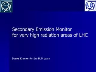
Very High Radiation Detector for the LHC BL M System based on S econdary E lectron Emission. Daniel Kramer , Eva Barbara Holzer, Bernd Dehning, Gianfranco Ferioli CERN AB-BI. LHC Beam Loss Monitoring system. ~ 3700 BLMI chambers installed along LHC

E N D
Very High Radiation Detector for the LHC BLM System based onSecondary Electron Emission Daniel Kramer, Eva Barbara Holzer, Bernd Dehning, Gianfranco Ferioli CERN AB-BI IEEE NSS 2007 D.Kramer
LHC Beam Loss Monitoring system • ~ 3700 BLMI chambers installed along LHC • ~ 280 SEM chambers required for high radiation areas: • Collimation • Injection points • IPs • Beam Dumps • Aperture limits • Main SEM requirements • 20 years lifetime (up to 70MGray/year) • Sensitivity ~3E4 lower than BLMI IEEE NSS 2007 D.Kramer
LHC Beam Loss Monitoring system • ~ 3700 BLMI chambers installed along LHC • ~ 280 SEM chambers required for high radiation areas: • Collimation • Injection points • IPs • Beam Dumps • Aperture limits • Main SEM requirements • 20 years lifetime (up to 70MGray/year) • Sensitivity ~3E4 lower than BLMI IEEE NSS 2007 D.Kramer
Secondary Emission Monitor working principle • Secondary Electron Emission is a surface phenomenon • Energy of SE (below ~ 50 eV, dominant for signal) is independent on primary energy • SE are pulled away by HV bias field (1.5kV) • Signal created by e- drifting between the electrodes • Delta electrons do not contribute to signal due to symmetry* Secondary electrons Bias E field Ti Signal electrode Ti HV electrodes Steel vessel (mass) < 10-4 mbar • VHV necessary to keep ionization inside the detector negligible • Very careful insulation and shielding of signal path to eliminate ionization in air (otherwise nonlinear response) • No direct contact between Signal and Bias (guard ring) IEEE NSS 2007 D.Kramer
Secondary Emission Monitor working principle • Secondary Electron Emission is a surface phenomenon • Energy of SE (below ~ 50 eV, dominant for signal) is independent on primary energy • SE are pulled away by HV bias field (1.5kV) • Signal created by e- drifting between the electrodes • Delta electrons do not contribute to signal due to symmetry* Secondary electrons Bias E field Ti Signal electrode Incoming particle Ti HV electrodes Steel vessel (mass) < 10-4 mbar • VHV necessary to keep ionization inside the detector negligible • Very careful insulation and shielding of signal path to eliminate ionization in air (otherwise nonlinear response) • No direct contact between Signal and Bias (guard ring) IEEE NSS 2007 D.Kramer
Secondary Emission Monitor working principle • Secondary Electron Emission is a surface phenomenon • Energy of SE (below ~ 50 eV, dominant for signal) is independent on primary energy • SE are pulled away by HV bias field (1.5kV) • Signal created by e- drifting between the electrodes • Delta electrons do not contribute to signal due to symmetry* Secondary electrons Bias E field Ti Signal electrode Incoming particle Ti HV electrodes Steel vessel (mass) < 10-4 mbar • VHV necessary to keep ionization inside the detector negligible • Very careful insulation and shielding of signal path to eliminate ionization in air (otherwise nonlinear response) • No direct contact between Signal and Bias (guard ring) IEEE NSS 2007 D.Kramer
Secondary Emission Monitor working principle • Secondary Electron Emission is a surface phenomenon • Energy of SE (below ~ 50 eV, dominant for signal) is independent on primary energy • SE are pulled away by HV bias field (1.5kV) • Signal created by e- drifting between the electrodes • Delta electrons do not contribute to signal due to symmetry* Secondary electrons Bias E field Ti Signal electrode Incoming particle Ti HV electrodes Steel vessel (mass) < 10-4 mbar • VHV necessary to keep ionization inside the detector negligible • Very careful insulation and shielding of signal path to eliminate ionization in air (otherwise nonlinear response) • No direct contact between Signal and Bias (guard ring) IEEE NSS 2007 D.Kramer
Secondary Emission Monitor working principle • Secondary Electron Emission is a surface phenomenon • Energy of SE (below ~ 50 eV, dominant for signal) is independent on primary energy • SE are pulled away by HV bias field (1.5kV) • Signal created by e- drifting between the electrodes • Delta electrons do not contribute to signal due to symmetry* Secondary electrons Bias E field Ti Signal electrode Incoming particle Ti HV electrodes Steel vessel (mass) Incoming particle < 10-4 mbar • VHV necessary to keep ionization inside the detector negligible • Very careful insulation and shielding of signal path to eliminate ionization in air (otherwise nonlinear response) • No direct contact between Signal and Bias (guard ring) IEEE NSS 2007 D.Kramer
SEM production assembly • All components chosen according to UHV standards • Steel parts vacuum fired • Detector contains 170 cm2 of NEG St707 to keep the vacuum < 10-4 mbar during 20 years • Pinch off after 350°Cvacuum bakeout and NEG activation (p<10-10mbar) • Ti electrodes partially activated (slow pumping observed) IEEE NSS 2007 D.Kramer
Simulations in Geant4 • Detailed Geometry of SEM F type implemented • Signal electrode covered by thin layer of TiO2 • Photo-Absorption-Ionization module used for production of delta electrons • QGSP_BERT_HP used as main physics list • Signal generation done by • calculating charge balance on signal electrode • recording “True SE” produced by custom generator • Production threshold for e+/e- set to 9m IEEE NSS 2007 D.Kramer
Semi empirical approach using simplified Sternglass formula • Secondary Emission Yield is proportional to electronic dE/dx in the surface layer • LS = (0.23 Ng)-1 • g = 1.6 Z1/310-16cm2 • “TrueSEY” of each particle crossing the surface boundary calculated and SE recorded with this probability • Correction for impact angle included in simulation • Fast electrons considered as other primaries Electronic energy loss Model calibration factor Penetration distance of SE Comparison => CF = 0.8 IEEE NSS 2007 D.Kramer
Simulated response curves for different particle types • Geant4 version 8.1.p01 • 30k primaries for each energy point • Longitudinal impact • Gaussian beam • r = 2mm e- absorbed in electrode IEEE NSS 2007 D.Kramer
400 GeV Beam scan in TT20 SPS line • Longitudinal impact of proton beam • r = 2mm • Chamber tilted by ~1° • Simulation sensitive to beam angle and divergence • Negative signal due to low energy e- from secondary shower IEEE NSS 2007 D.Kramer
400 GeV Beam scan in TT20 SPS line • Longitudinal impact of proton beam • r = 2mm • Chamber tilted by ~1° • Simulation sensitive to beam angle and divergence • Negative signal due to low energy e- from secondary shower chamber diameter IEEE NSS 2007 D.Kramer
Prototype tests with 63MeV cyclotron beam in Paul Scherer Institute PSI proton beam 62.9MeV BLMS prototypes F & C Type HV dependence of SEY • Prototype C -> more ceramics inside (no guard ring) • Prototype F -> close to production version • Current measured with electrometer Keithley 6517A • HV power supply FUG HLC14 • Pattern not yet fully understood • Not reproduced by simulation • High SE response if U_bias > 2V • Geant4.9.0 simulated SEY = 25.50.8% IEEE NSS 2007 D.Kramer
Measurements in PS Booster Dump line with 1.4 GeV proton bunches • Older prototype used - Type C • Profiles integrated with digital oscilloscope • 1.5kV bias voltage • 80m cable length • 50 termination • Single bunch passage • SEY measurement • 4.9 0.2% • Geant4.9.0 simulation • 4.2 0.5% Normalized response IEEE NSS 2007 D.Kramer
Measurements in PS Booster Dump line with 1.4 GeV proton bunches SEM response to single proton bunch of 2.16 1013 protons with 160ns length • BLMS compared to reference radiation monitor ACEM (Aluminum Cathode Electron Multiplier tube) • ACEM not directly in the beam • Rise/fall time < 50 ns • Dominated by unknown intensity distribution • Normalized intensity 1.3 1019p+/s IEEE NSS 2007 D.Kramer
Conclusions • The BLMS detector was successfully tested in different proton beams • Geant4 simulations are in good agreement with these experiments • => chosen model is validated • Sign change of output current possible under very specific circumstances • Verification measurements in mixed radiation field of LHC test collimation area in SPS are ongoing • 360 BLMS Detectors were produced in IHEP Protvino and will be tested soon IEEE NSS 2007 D.Kramer