Download
1 / 17
170 likes | 578 Views
Robotic Process for Installing Hull Inserts. March 12-14, 2019. Charleston, SC Presented by: Ryan Taylor & Joseph Meeker DCN# 43-5020-19. Prepared under ONR Contract N00014-16-D-4001 as part of the Navy ManTech Program. Agenda. Current problem installing hull inserts Purpose of project

E N D
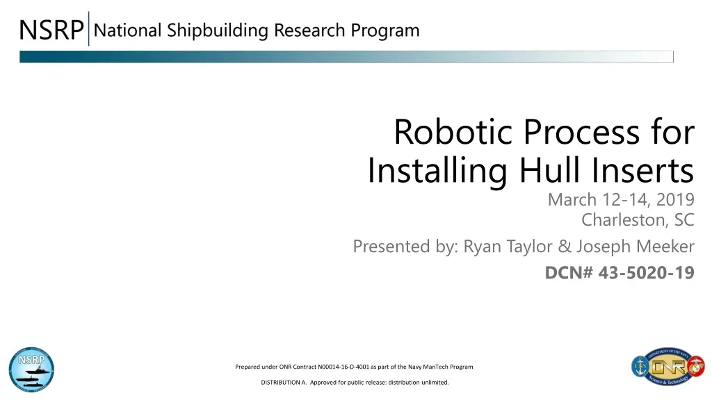
Robotic Process for Installing Hull Inserts March 12-14, 2019 Charleston, SC Presented by: Ryan Taylor & Joseph Meeker DCN# 43-5020-19 Prepared under ONR Contract N00014-16-D-4001 as part of the Navy ManTech Program
Agenda • Current problem installing hull inserts • Purpose of project • Project overview • Project objectives • Missile Tube to Keel Process (MT2K) • Project expectations • Phase overviews • Risk • Schedule
Problem • The installation of hull inserts in VIRGINIA Class Submarines (VCS) requires approximately 45,000 labor hours per hull. • The COLUMBIA Class Submarine (CCS) is expected to have a more inserts. • In the current process, the trades locate and layout the insert on the hull, cut the opening in the hull with oxy-fuel cutting, bevel the hull weld joint with oxy-fuel cutting, grind to desired surface finish, and semi-automatically weld the insert into place. • Complex welds due to constantly varying bevel angles to be consisted with the curvature of the hull. • *Often requires re-work. • *No commercial off the shelf technology available for hull insert cutting, beveling, grinding, and welding.
Purpose • Improve the hull insert installation processes for VCS and CCS. • Investigate, develop, and prototype a robotic hull insert installation system that increases weld quality. • Reduce labor hours from the following: • Locating/layout • Cutting/Beveling • Fitting • Welding • Paradigm shift in robotic manufacturing • Ability to bring robot to the part rather bringing the part to the robot • Large unique parts with high tolerances and critical dimensions • Versatile automation in variable work environments • Ex: Bring robot to the hull rather than assembly line fashion in automotive industry • Repeatable and predictable process • Support critical dimensions • Produce X-ray quality welding
Project Overview • 30 Month Project • 3 Phases • Phase I – Identify System Requirements • 5/7/18 – 10/5/18 • Phase II – Demonstrate System Functionality via Simulation • 10/8/18 – 9/13/19 • Phase III – Demonstrate Robotic Hull Installation Process Using a Prototype System in the Shipyard • 9/16/19 – 11/16/20 • 5-year ROI ≈ 2
Objectives • System will be designed to robotically locate/layout, cut, bevel, grind, and weld hull penetration and their mating inserts • First Article Cutting System (FACS) purchased for the MT2K project will be used to prototype the hull insert installation processes • Facility has FACS readily available used for prototyping. • Requirements will be defined for system/weld procedure qualification • Business case will be developed to support system procurement • Implementation plan will be created • *Leverage MT2k technology and apply to hull inserts project
Missile Tube to Keel Process • The MT2K process pioneered the development of a modular missile tube construction, with an estimated $45M cost savings per ship. • First large-scale use of robotic cutting and welding for submarines. • This design utilized 4 different vendor sources. • Fixture design and manufacture • As-Built Data Analysis • Robotic Cutting/ Beveling • Robotic welding
Missile Tube to Keel Process • The MT2k process involves accuracy control to map out the keel and missile tube utilizing 3D metrology software. • Data obtained from software is used to identify as-built configuration to accurately define and create the robotic cut/ bevel path. • The surface is then prepared for welding, using specific grind media to achieve repeatable accuracy. • Welding is then accomplished by using an adaptive path planning process to deposit multi-pass/ multilayer welds. • *Multiple geometrical challenges will be faced in integrating an as built system for this Hull Inserts task.
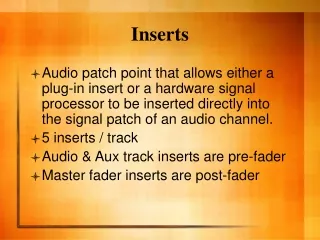
Cutting and Welding • Cutting application utilizes a high pressure Oxy-Fuel cutting configuration. • Welding is achieved by remote operation though different arc and surveillance cameras. • Operators on both systems have the ability to view their parameters to ensure optimal operation. • This will be the same methodology for Hull Inserts • *However a modified approach may be required due to differences in joint, bevel, and geometrical configurations .
First Article Cutting System • During the prototyping of the hull inserts project the FACS used in the MT2k will be modified by outfitting a welding torch to the cutting system. • An ABB IRB 4600 Industrial Robot will be used for development of this phase. • 6 axis system with a payload up to 130lbs and a working range up to 8 ft. • The final purchased system may not be the same system used during prototyping. ABB IRB 4600 Robot
Hull Insert Expectations • Reduction in total hours by: • having robot scan as-built geometry of the insert to then match the robotically cut hole in hull. • Reducing weld time due to the majority of the weld being completed robotically. • Robotically beveling the outsourced inserts . • Accurately locate the system on the side of the hull relative to the ships x, y, z coordinate system and to then accurately locate and cut the hole for the hull insert • MT2K project increased efficiency (~50% for welding & ~75% for cutting). • 2 Robots, 1 for cutting & 1 for welding.
Phase I • Identify System Requirements (5/7/18 – 10/5/18) • Task 1 – Project Initiation • Electric Boat hosted kick-off meeting • Technology Transition Plan feedback provided to CNM • Task 2 – Define Application Criteria for Hull Insert Installation Processes • Identify and categorize hull inserts candidates • Baseline of current process and define future state • Down select a target joint for system development • Reporting • Task 3 – Technical Requirements Definition • Baseline current MT2k system • Market survey of robotic capabilities • Develop System Functional Specifications • Reporting • Task 4 – Phase I Reporting • Project team recommended a “Go” for Phase II execution • Phase I review hosted by EB
Phase II • Demonstrate System Functionality via Simulation (10/8/18 – 9/13/19) • Task 5 – Determine LOE to Modify First Article Cutting System for the MT2k Project • Task 6 – Software Modification • Task 7 – Develop Simulation and Test Plan • Task 8 – Phase II Reporting
Phase III • Demonstrate Robotic Hull Installation Process with Prototype System in Shipyard (9/16/19 – 11/16/20) • Task 9 – Perform Cutting and Grinding Testing • Task 10 – Perform Bevel Testing • Task 11 – Perform Weld Testing • Task 12 – Create and Execute Qualification Support Test Plan • Task 13 – Verify System Scalability • Task 14 – Develop Implementation Plan • Task 15 – Final Reporting
Project Team Neil Graf – Program Officer Dale Orren – Deputy Director Bobby Mashburn – Project Manager Ryan Frankart – Project Technical Representative Steve Fuqua – PMS 397 Larry Becker – BAH Charles McNamara – PMS 450 Dave Hart – LCE Matt Sinfield – NSWCCD 05P TA Jeff Farren – NSWCCD 05P TA Ned Kaminski – Technical SME and Lead Process Engineer Derek McKee – Lead Ryan Taylor – Co-Lead John Iraci – ManTech Program Manager Amanda Scott – ManTech Coordinator Nancy Porter – Sr. Project Manager/Welding Engineer Bill Tomich – Welding Engineer Mike Carney – Welding Engineer Steve Blevins – Project Manager/Welding Engineer
Questions Ryan Taylor ManTech Technical Lead General Dynamics, Electric Boat Corp. 401-268-3578 rtaylor4@gdeb.com Derek Mckee ManTech Technical Lead General Dynamics, Electric Boat Corp. 401-268-3676 dmckee@gdeb.com John Michael Iraci ManTech Program Manager General Dynamics, Electric Boat Corp. 860-867-3519 jiraci@gdeb.com DISTRIBUTION A. Approved for public release: distribution unlimited.