Download
1 / 7
70 likes | 380 Views
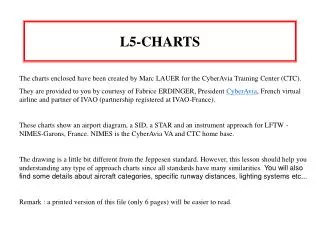
L5-CHARTS The charts enclosed have been created by Marc LAUER for the CyberAvia Training Center (CTC). They are provided to you by courtesy of Fabrice ERDINGER, President CyberAvia , French virtual airline and partner of IVAO (partnership registered at IVAO-France).

E N D
L5-CHARTS The charts enclosed have been created by Marc LAUER for the CyberAvia Training Center (CTC). They are provided to you by courtesy of Fabrice ERDINGER, President CyberAvia, French virtual airline and partner of IVAO (partnership registered at IVAO-France). These charts show an airport diagram, a SID, a STAR and an instrument approach for LFTW - NIMES-Garons, France. NIMES is the CyberAvia VA and CTC home base. The drawing is a little bit different from the Jeppesen standard. However, this lesson should help you understanding any type of approach charts since all standards have many similarities. You will also find some details about aircraft categories, specific runway distances, lighting systems etc... Remark : a printed version of this file (only 6 pages) will be easier to read.
ARP coordinates (= airfield coordinates). Airport Diagram ALT - AD: 308 ft GARONS Gnd : 121.800 NIMES – Garons (LFTW) 43°45’27’’ N - 004°25’03’’ E Radio frequency to be used. Magnetic declinaison (calculated in 1995) = 1° west. Rwy 18 is equipped with approach lights. 10 02 2000 DEC 1° W (95) 178° Threshold 18 altitude. MM CABLE NIMES is a mixed civilian/military airfield. Two cables are available for hook equipped aircraft. GP = Glide Path Position of GP antennas (part of the ILS materializing the glide path). Milatary Area Civilian Area ILS - GP PKG MIL 302 PAPI = Precision Approach Path Indicator. The slope here is 3°. PAPI 3° TERMINAL H = Helipad NIMES has two helipads. One for military helicopters just in front of the tower. One for Securite Civile and civilian helicopters on the east side of the runway. CABLE Runway length and width (could be in feet) HANGARS HANGARS CYBERAVIA HANGARS TODA = Take Off Runway Available 2440 m TODA = Take Off Distance Available 2440 m ASDA = Acceleration-Stop Dist. Avail. 2530 m. LDA = Landing Distance Available 2440 m These indications are important when there are displaced thresholds (not the case here). H SECURITE CIVILE TWR HANGARS ARP H RUNWAY 2440 x 45 m PAPI 3° PKG MIL ARP = Aerodrome Reference Point CABLE LLZ = Localizer Position of LLZ antennas (part of the ILS materializing the runway centerline) . 308 NIM TACAN Runway surface = concrete Runway strength = 55 t by gear ILS - LLZ 500 m 0 1000 m HI = High Intensity LI = Low Intensity LI lighting is omnidirectional and has only one intensity (low). HI lighting is unidirectional and has several intensities (very low-low-medium-high-very high) 900 m = approach lights length. NIL = nothing – none for rwy 36. 358° ALTITUDES IN FEET • Airfield open to those categories : • - A like helicopters, Pa28, C182, DHC6 • - B like B1900, Learjet, C160, E121 • - C like A310, B727/737, MD80 • D like A330/340, B747/767, DC10 • Do not take-off if vis < 250 m (cat ABC) or 300 m (cat D). • Aircraft categories are defined according to landing speed Vat = 1.3 x Vso (Vso is stall speed with gear and full flaps out) : • A – Vat < 90 kt • B – Vat 91 to 120 kt • C – Vat 121 to 140 kt • D – Vat 141 to 165 kt • E – Vat > 166 kt (Concorde) LIGHTING DISTANCES Surface TKOF MINIMA (meters) Rwy Approach Rwy TORA TODA ASDA LDA Strength Cat A Cat B Cat C Cat D HI OACI Concrete 18 900 m HI/LI 2440 2440 2530 2440 250 250 250 300 36 NIL HI/LI 2440 2440 2530 2440 55 RCWT 250 250 250 300 OBSERVATIONS : MISC : RWY 18/36 :Threshold HI/LI REIL HI/LI Cables : 280 m beyond thld 18 260 m beyond thld 36 TWY : Concrete PKG : Concrete Thld 18 : 43°46’08.6’’ N - 004°25’00.2’’ E Thld 36 : 43°44’51.3’’ N - 004°25’05.8’’ E FOR SIMULATION PURPOSES ONLY DO NOT USE FOR REAL NAVIGATION REIL = Rwy End Identifier Lights
Minimum Vectoring Altitudes NIMES – Garons (LFTW) MVA MVA = Minimum Vectoring Altitudes 08 02 2000 TA = Transition Altitude Change alt setting from QNH to standard 1013 or 29.92 when crossing TA (during climb). TA : 5000 DEC 1° W (95) MTL 112.70 MEN 115.30 Magnetic declinaison (calculated in 1995) = 1° west. CTA = Control Area Controlled airspace usually high and established above a CTR. When not a CTA, this kind of airspace is usually a TMA = Terminal Control Area. RHONE S/CTAs (there are several) extend from 2000 ft to FL 195. CTR = Control Zone Controlled airspace including one or several airports and which lower limit is the surface. NIMES S/CTR extends from surface to 2000 ft. S/ = Specialized Specialized means the airspace are managed by military controllers for both military and civilian aircraft. RHONE S/CTA is under the responsability of ISTRES APP (French Air Force). NIMES S/CTR is under the responsability of NIMES APP (French Navy). S/CTA RHONE - S/CTR NIMES 6600 35 NM MVA These are minimum vectoring altitudes into RHONE S/CTA and NIMES S/CTR. That means the controller can’t give any altitude clearance lower than the MVA indicated for each sector. An aircraft coming from VALMA will be initially cleared to 6600 ft until it reaches 35 NM inbound. Then to descend lower wait : - 35 NM for 5000 ft. - 25 NM for 3300 ft. - 20 NM for 3000 ft . - 14 NM for 2000 ft. These MVA ensure the aircraft will not touch the ground when approaching. This chart is more useful for controllers than for pilots. However, pilots can check controllers are not bringing them too far and too low. VALMA 25 NM 3300 5000 20 NM MOLEN 3000 14 NM NG 354 NIMES-GARONS LUNEL 2000 FJR 117.40 VARES RHONE NIM Ch53X DME 111.60 MARRI MTG 117.30 SALIN FOR SIMULATION PURPOSES ONLY DO NOT USE FOR REAL NAVIGATION ALTITUDES IN FEET
Instrument Approach CAT. A B C D NIMES – Garons (LFTW) STAR Airfield open to those categories : - A like helicopters, Pa28, C182, DHC6 - B like B1900, Learjet, C160, E121 - C like A310, B727/737, MD80 - D like A330/340, B747/767, DC10 STAR = Standard Terminal Arrival Route Standard Arrival Procedures 08 02 2000 TA : 5000 DEC 1° W (95) MTL 112.70 TA = Transition Altitude Transition level provided by ATC according to TA and altimeter setting. Change from 1013 or 29.92 to local altimeter setting given by ATC (during descent). Magnetic declinaison (calculated in 1995) = 1° west. MEN 115.30 MOLEN 2 MOLEN 2 For this STAR : - from MTL, hdg 202° to MOLEN descending 3000 ft mini. - passing MOLEN (19 NM NIM), maintain hdg 202° and descend 2000 ft mini to NG. See also details about holding pattern entries on a following slide. 131° 32 6600 247° MTL 35 DA 402 440359N 0040832E VALMA 2 Name of the STAR. When authorized to proceed according to a STAR, you are supposed to know it (if not, ask for radar vectors) and follow chart instructions. Here is VALMA 2 : - from MEN, hdg 131° to VALMA descending 6600 ft mini. - passing VALMA, maintain hdg 131° and descend 5000 ft mini. - at 25 NM inbound NIM, descend 3000 ft to NG. You must comply with these instructions unless otherwise instructed by the controller (for regulation purposes for instance). However, never descend below the altitude specified for the route you are on. They have been calculated to avoid collision with the ground. Distances are indicated also : MEN - VALMA = 35 NM VALMA - NG = 35 NM 3000 VALMA 441400N 0034721E 202° 131° 5000 VALMA 2 NG 354 435126N 0042423E 19 NM NIM MOLEN 440319N 0043046E 25 NM NIM 2000 35 3000 13 HOLDING L NG 2000 - FL 70 Inbnd 178° Left 1 min - 220 KIAS 2000 Reporting points coordinates are indicated so that you can program your FMS or GPS. NIM Ch53X DME 111.60 15 050° 2000 LUNEL 2 LUNEL 434122 0040845E 10 34 2000 29 RHONE 2 2000 FJR 117.40 328° 355° RHONE 442309N 0045040E 119° FJR 25 NM 271° MTG MARRI 2 This STAR is an alternative to RHONE 2 when area R108A is active. RHONE 2 route crosses the R108A area belonging to ISTRES APP. In case the area is active, aircraft coming from MTG can’t use RHONE 2 STAR, they are rerouted via MARRI 2. MARRI 432305N 0042827E If R108 A active Holding pattern specifications. - L NG = Locator named NG - minimum altitude = 2000 ft - maximum level = FL 70 - inbound leg = hdg 178° - left pattern (counter clockwise) - leg length : 1 min - max IAS in knots : 220 MTG 117.30 MARRI 2 SALIN FOR SIMULATION PURPOSES ONLY DO NOT USE FOR REAL NAVIGATION ALTITUDES (HEIGHTS) IN FEET
LOCATOR - ILS procedure for Rwy 18. Airfield open to those categories : - A like helicopters, Pa28, C182, DHC6 - B like B1900, Learjet, C160, E121 - C like A310, B727/737, MD80 - D like A330/340, B747/767, DC10 Instrument Approach CAT. A B C D NIMES – Garons (LFTW) L - ILS RWY 18 ILS frequency and callsign APP : RHONE Control 120.350 APP : GARONS Approach 124.900 TWR : GARONS Tower 123.200 08 02 2000 ILS NG 109.10 DEC 1°W (95) • Minimum Holding Altitude 2000 ft • Max IAS is 220 kt • Max holding altitude is 7000 ft • Inbound leg 178°, left turn • - Outbound leg 378°, 1 minute Radio frequencies to be used 189° ALT - AD : 308, Thld : 302 MHA 2000 Max IAS : 220 kt ZP : 7000 Minimum Safe Altitude For instance, if joining NG with a heading between 189° and 309°, the minimum altitude you can descend to and remain sure not to hit the ground or an obstacle within 25 NM from NG is 3000 ft. 5000 NIMES TACAN. A TACAN is a military VOR/DME. Military aircraft use the TACAN channel 53X for radials and DME (doesn’t work in FS) Civilian aircraft can only use the DME signal from 111.6 on NAV 1 or 2 (radials not available). Sometimes, a VORTAC (mixed TACAN and VOR, not the case here) is available. Civilians get radials from VOR and DME from TACAN. 3000 2000 178° 059° 309° 1 min 2000 358° MSA 25 NM NG IAF = Initial Approach Fix This is the start point of an instrument approach procedure. Very often, the IAF is also a fix for the holding pattern as you can see here. The IAF is the Locator NG, 354 kHz. IAF OM NG 354 178° MM NIM Ch53X DME 111.60 The continuous lines are for the arrival procedure and the holding pattern. The dotted line is for the missed approach procedure. A maximum speed (IAS) is often specified for the missed approach (220 kt here). MAPT = Missed Approach Point Start point of the missed approach procedure (for LOC GS out apch). The MAPt is the Middle Marker (MM). OM = Outer Marker 2 NM NIM Max IAS 220 kt ALTITUDES (HEIGHTS) IN FEET Missed approach details The missed approach procedure is always fully described. FAF = Final Approach Fix This is the point at which you have to start the descent when proceeding for a localizer approach (glide slope unserviceable). The FAF is NG again. TA : 5000 FAF LOC GS out NG MM MAPT LOC gs out NIM OM Missed Apch : Climb straight ahead to D2.0 NIM TAC then turn right to NG (max IAS 220 kt) climbing to 2000 ft (1698). LEFT 2000 (1698) Circle-to-land (also known as CIRCLING) A maneuver executed when approaching a runway and landing on another one. NIMES has no instrument procedures for Rwy 36. If wind is for runway 36 and weather is bad (no visual approach available), you have to perform the instrument approach Rwy 18 and, instead of landing with tail wind, break right and land runway 36. This is a circle-to-land. 178° MDA 3° 5.2 % 1550 (1248) DA = Decision Altitude (for ILS) If you don’t have the runway in sight (or cannot land safely) when reaching 510 ft, execute the missed approach procedure. Minimum visibility for this procedure is 550 meters MDA = Minimum Descent Altitude (for LOCALIZER apch, Glide Slope out) Idem when reaching 590 feet. Minimum visibility is 800 or 1200 m DA Distance Rwy 18 (NM) 5.3 3.7 0.5 Distance NIM TACAN (NM) 6.7 5.1 1.9 DA / MDA in feet, RVR/VIS in meters CAT A B C D DA 510 RVR 550 MDA 590 RVR 800 1200 MDA 740 810 930 1010 VIS 1500 1600 2400 3600 FOR SIMULATION PURPOSES ONLY DO NOT USE FOR REAL NAVIGATION ILS LOC (GS out) Circle-to-land Observations : Circling maneuvers prohibited east of airport 70 kt 85 kt 100 kt 115 kt 130 kt 160 kt 185 kt OM–Rwy 18 3.7 NM 3 min 10 2 min 37 2 min 13 1 min 56 1 min 42 1 min 23 1 min 12 Time necessary for flying from outer marker to threshold runway 18. Example : 1 min 56 sec at 115 kt
ENTRY INTO THE HOLDING According to your heading for joining the IAF, you can start the approach procedure directly or you have to execute a maneuver to bring your aircraft towards the IAF on a heading that enables you to start the approach procedure. You may have the same situations for entering a holding pattern. There are 3 entry maneuvers according to the sector you are coming from. These sectors are defined according to a 70° angle with the inbound leg, on the holding side as shown below. Let’s see some examples with the IAF NG, which is also the fix for the holding pattern : MTL-MOLEN Hdg 202° 70° 70° 70° 1 MEN-VALMA Hdg 131° 30° 178° 178° 178° 358° IAF IAF CM 369 Hdg 263° NG 354 358° 358° NG 354 OM 178° OM OM 178° 178° 3 IAF MM 70° NG 354 MM MM 2 2 NM NIM FJR-LUNEL Hdg 050° RHONE Hdg 328° 2 NM NIM MARRI Hdg 355° Max IAS 220 kt Max IAS 220 kt Max IAS 220 kt SECTOR 1 – DIRECT ENTRY When coming from MTL-MOLEN or MEN-VALMA When reaching the IAF (NG), start the procedure if authorized by ATC or perform a holding pattern. SECTOR 2 – OFFSET ENTRY When coming from FJR-LUNEL When reaching the IAF (NG), choose a heading giving a 30° angle with the inbound leg, on the holding side (here hdg 028°). Maintain this heading (028°) as long as specified for the holding (1 min here) then turn to join the inbound leg (here, a left turn to NG). When reaching the IAF again (NG), start the procedure if authorized by ATC or perform a holding pattern. SECTOR 3 – PARALLEL ENTRY When coming from RHONE, MARRI or CM When reaching the IAF (NG), take the outbound heading as long as specified for the holding (358° for 1 min here). Then turn on the holding side to join directly the IAF or holding fix (NG). When reaching the IAF again (NG), start the procedure if authorized by ATC or perform a holding pattern.
Instrument Approach CAT. A B C D NIMES – Garons (LFTW) SID RWY 18 SID = Standard Instrument Departure Also known as DP (Departure Procedure) Airfield open to those categories : - A like helicopters, Pa28, C182, DHC6 - B like B1900, Learjet, C160, E121 - C like A310, B727/737, MD80 - D like A330/340, B747/767, DC10 08 02 2000 TA : 5000 DEC 1° W (95) MTL 112.70 Magnetic declinaison (calculated in 1995) = 1° west. TA = Transition Altitude Change alt setting from QNH to standard 1013 or 29.92 when crossing TA (during climb). MEN 115.30 DA 402 440359N 0040832E 32 Reporting points coordinates are indicated so that you can program your FMS or GPS. MOLEN 1 247° MTL 35 VALMA 441400N 0034721E 022° VALMA 1 Name of the SID. When authorized to proceed according to a SID, you are supposed to know it (if not, ask for radar vectors) and follow chart instructions. Here is VALMA 1 : - climb straight ahead. - when passing 700 ft QNH (400 ft QFE), right turn heading 339° towards DA. - continue climbing up to FL given in departure clearance. - intercept MEN radial 131° (at 18 NM from NIM) and continue on heading 311° to VALMA. - at VALMA, maintain haeding 311° to MEN. Distances are indicated also : Take-off - R131° MEN = 26 NM 18 NM NIM - VALMA = 22 NM VALMA - MEN = 35 NM Your departure clearance could be : « FL 90 VALMA 1 squawk 1501 » This means your are cleared for a standard departure VALMA 1, climbing up to FL 90 and squawking 1501. 311° 22 VALMA 1 19 NM NIM NG 354 435126N 0042423E MOLEN 440319N 0043046E 18 NM NIM 13 131° MEN 339° 26 15 NIM Ch53X DME 111.60 MARRI 1 This an alternative SID when the R108A area is active. RHONE 1 route crosses the R108A area belonging to ISTRES APP. In case the area is active, aircraft departing to MTG can’t use RHONE 1 SID, they are rerouted via MARRI 1. 279° 080° LUNEL 1 16 LUNEL 434122N 0040845E 10 31 230° 22 RHONE 1 FJR 117.40 700 (400) 148° 175° RHONE 442309N 0045040E 119° FJR 25 NM 271° MTG MARRI 432305N 0042827E If R108 A active MTG 117.30 MARRI 1 SALIN FOR SIMULATION PURPOSES ONLY DO NOT USE FOR REAL NAVIGATION ALTITUDES (HEIGHTS) IN FEET