Download
1 / 36
360 likes | 658 Views
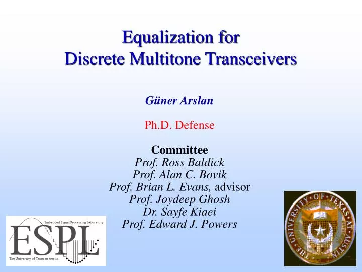
Equalization for Discrete Multitone Transceivers. Güner Arslan Ph.D. Defense Committee Prof. Ross Baldick Prof. Alan C. Bovik Prof. Brian L. Evans, advisor Prof. Joydeep Ghosh Dr. Sayfe Kiaei Prof. Edward J. Powers. Receive bit stream. Transmit bit stream. Transmitter. Channel.

E N D
Equalization for Discrete Multitone Transceivers Güner Arslan Ph.D. Defense Committee Prof. Ross Baldick Prof. Alan C. Bovik Prof. Brian L. Evans, advisor Prof. Joydeep Ghosh Dr. Sayfe Kiaei Prof. Edward J. Powers
Receive bit stream Transmit bit stream Transmitter Channel Receiver TEQ Outline • Introduction to high-speed wireline digital communications • Problem: Increase ADSL transceiver bit rate by increasing performance of the time-domain equalizer (TEQ) in the receiver • Contribution #1: New model for equalized channel • Contribution #2: Optimal channel capacity TEQ • Contribution #3: Closed-form near-optimal TEQ • Simulation results • Summary and future work
Introduction Residential Applications Business Applications
Standards for High-Speed Digital Communications Courtesy of Shawn McCaslin (Cicada Semiconductor, Austin, TX)
2.1 1.7 1 1 1 1 1 .7 .4 .1 -1 Intersymbol Interference (ISI) • Ideal channel • Impulse response is an impulse • Frequency response is flat • Non-ideal channel causes ISI • Channel memory • Magnitude and phase variation • Received symbol is weighted sum of neighboring symbols • Weights are determined by channel impulse response = * Receivedsignal Channel Transmit signal Threshold at zero 1 1 1 1 Detected signal
Combat ISI with Equalization • Problem: Channel frequency response is not flat • Solution: Use equalizer to flatten channel frequency response • Zero-forcing equalizer • Inverts channel • Flattens frequency response • Amplifies noise • Minimum mean squared error (MMSE) equalizer • Optimizes trade-off between noise amplification and ISI • Decision-feedback equalizer • Increases complexity • Propagates error MMSE Equalizer frequency response Zero-forcing Equalizer frequency response Channel frequency response Magnitude (dB) Frequency
Multicarrier Modulation • Divide broadband channel into many narrowband subchannels • No intersymbol interference (ISI) in subchannels if channel gain is constant in every subchannel • Discrete Multitone (DMT) modulation • Multicarrier modulation based on fast Fourier transform (FFT) • Standardized for ADSL and proposed for VDSL channel frequency response magnitude carrier subchannel frequency
Multicarrier Modulation • Advantages • Efficient use of bandwidth without full channel equalization • Robust against impulsive noise and narrowband interference • Dynamic rate adaptation • Disadvantages • Transmitter: High signal peak-to-average power ratio • Receiver: Sensitive to frequency and phase offset in carriers • Active areas of research • Pulse shapes of subchannels (orthogonal, efficient realization) • Channel equalizer design (increase capacity, reduce complexity) • Synchronization (timing recovery, symbol synchronization) • Bit loading (allocation of bits in each subchannel)
Eliminating ISI in DMT copy copy • Convolve stream of samples with channel • Symbols are spread out in time • No ISI if channel length is shorter than v+1 samples • Symbols are distorted in frequency • Cyclic prefix converts linear convolution into circular convolution • Division in FFT domain can undo distortion if channel length is less thanv+1 samples • Time domain equalizer shortens channel length • Frequency domain equalizer inverts channel frequency response s y m b o l ( i+1) CP CP s y m b o li CP: Cyclic Prefix v samples N samples
Discrete Multitone Transmitter and Receiver N/2 subchannels N subchannels (N = 512 for ADSL) DAC and transmit filter serial to parallel QAM encoder mirror data and N-IFFT add cyclic prefix parallel to serial TRANSMITTER channel RECEIVER N/2 subchannels N subchannels parallel to serial QAM decoder invert channel = frequency domain equalizer N-FFT and remove mirrored data serial to parallel remove cyclic prefix receive filter and ADC TEQ time domain equalizer
Problem Definition and Contributions • Problem: • Find a TEQ design method that maximizes channel capacity at the TEQ output • Proposed solution • Decompose equalized channel into signal, noise, and ISI paths • Model subchannel SNR based on this decomposition • Write channel capacity as a function of TEQ taps • Develop design methods to maximize channel capacity • Contributions • A new model for subchannel SNR • Optimal maximum channel capacity (MCC) TEQ design method • Near-optimal minimum ISI TEQ design method
nk rk yk ek xk w h + + - b z- zk Minimum Mean Squared Error (MMSE) MethodChow, Cioffi, 1992 • Minimize mean squared error E{ek} where ek=bk-- hk*wk • Chose length of bk to shorten length of hk*wk • Disadvantages • Does not consider channel capacity • Zeros low SNR bands • Deep notches in equalizer frequency response
w h Maximum Shortening SNR (MSSNR) MethodMelsa, Younce, Rohrs, 1996 • For each possible position of a window of +1 samples, • Disadvantages • Does not consider channel capacity • Requires Cholesky decomposition and eigenvector calculation • Does not take channel noise into account
Capacity of a Multicarrier Channel • Each subchannel modeled as white Gaussian noise channel • Define geometric SNR • Channel capacity of a multicarrier channel
Maximum Geometric SNR MethodAl-Dhahir, Cioffi, 1996 • Maximize approximate geometric SNR • Disadvantages • Subchannel SNR definition ignores ISI • Objective function ignores interdependence of b and w • Requires solution of nonlinear constrained optimization problem • Based on MMSE method: same drawbacks as MMSE method • Ad-hoc parameter MSEmax has to be tuned for different channels nk rk xk ek w h + + - b z- zk
Delay CP CP Contribution #1New Subchannel Model: Motivating Example • Received signal • x is transmitted signal • Symbols ab • Symbol length • N = 4 • Length of • L = 4 • Cyclic prefix • v = 1 • Delay • = 1 Tail ISI signal ISI noise
gk 1 ... k Contribution #1Proposed Subchannel SNR Model • Partition equalized channel into signal path, ISI path, noise path nk rk yk xk h w + xk h w x Signal gk xk h w x ISI 1-gk nk w noise
Contribution #1Subchannel SNR Definition • SNR in i th subchannel is defined as
qiH Sx,i H HT qi Ai = Sn,i Sx,i qiH qiH H HT qi = qi Bi + D GT G DT FT F Contribution #2Optimal Maximum Channel Capacity (MCC) TEQ • Channel capacity as a nonlinear function of equalizer taps • Maximize nonlinear function to obtain the optimal TEQ • Good performance measure for any TEQ design method • Not an efficient TEQ design method in computational sense
Contribution #3Near-optimal Minimum-ISI (min-ISI) TEQ • ISI power in ith subchannel is • Minimize ISI power as a frequency weighted sum of subchannel ISI • Constrain signal path gain to one to prevent all-zero solution • Solution is a generalized eigenvector of X and Y • Possible weightings • Performance virtually equal to that of the optimal method • Generalizes MSSNR method by weighting in frequency domain
Contribution #3Min-ISI TEQ vs. MSSNR TEQ • Min-ISI weights ISI power with the SNR • Residual ISI power should be placed in high noise frequency bands
Contribution #3Efficient Implementations of Min-ISI Method • Generalized eigenvalue problem can solved with generalized power iteration: • Recursively calculate diagonal elements of X and Y from first column [Wu, Arslan, Evans, 2000]
Bit Rate vs. Number of TEQ Taps • Min-ISI, MCC, and MSSNR perform close to Matched Filter Bound (MFB) even with small TEQ sizes • Geometric and MMSE TEQ require 20 taps to achieve 90% of MFB performance • Geometric TEQ gives little improvement over MMSE TEQ • Two-tap min-ISI TEQ outperforms 21-tap MMSE TEQ TEQ taps cyclic prefix () 32 FFT size (N) 512 coding gain 4.2 dB margin 6 dB input power 14 dBm noise power -113 dBm/Hz, crosstalk noise 10 ADSL disturbers
Bit Rate vs. Number of TEQ Taps • Min-ISI and MCC give virtually same performance • Min-ISI and MCC outperform MSSNR by 2% • 9 taps is enough for best performance for min-ISI, MCC, and MSSNR TEQs • No performance gain for more than 9 taps TEQ taps cyclic prefix () 32 FFT size (N) 512 coding gain 4.2 dB margin 6 dB input power 14 dBm noise power -113 dBm/Hz, crosstalk noise 10 ADSL disturbers
Bit Rate vs. Cyclic Prefix Size • Min-ISI, MCC, and MSSNR perform close to MFB • Geometric and MMSE TEQ require cyclic prefix of 30 samples • Geometric TEQ gives worse performance for short cyclic prefix • Performance drops because cyclic prefix does not carry new information • MSSNR does not work for cyclic prefix smaller than the number of TEQ taps TEQ taps 17 FFT size (N) 512 coding gain 4.2 dB margin 6 dB input power 14 dBm noise power -113 dBm/Hz, crosstalk noise 10 ADSL disturbers
Simulation Results • Min-ISI, MCC, and MSSNR require cyclic prefix of 17 samples to hit matched filter bound performance • Geometric and MMSE TEQs do not work with 2 taps even with a cyclic prefix of 32 samples • Geometric TEQ gives lower performance for small cyclic prefix length • Min-ISI TEQ with 3-sample cyclic prefix outperforms MMSE TEQ with 32-sample cyclic prefix TEQ taps 2 FFT size (N) 512 coding gain 4.2 dB margin 6 dB input power 14 dBm noise power -113 dBm/Hz, crosstalk noise 10 ADSL disturbers
Simulation Results for 17-tap TEQ Cyclic prefix length of 32 FFT size (N) 512 Coding gain 4.2 dB Margin 6 dB Input power 14 dBm Noise power -113 dBm/Hz Crosstalk noise 10 ADSL disturbers
Simulation Results for Two-Tap TEQ Cyclic prefix length of 32 FFT size (N) 512 Coding gain 4.2 dB Margin 6 dB Input power 14 dBm Noise power -113 dBm/Hz Crosstalk noise 10 ADSL disturbers
Summary • Design TEQ to maximize channel capacity • No previous method truly maximizes channel capacity • New subchannel SNR model • Partitions the equalized channel into signal, noise, and ISI paths • Enables to write channel capacity as a function of equalizer taps • New maximum channel capacity TEQ design method • Good benchmark for all design methods • Requires nonlinear optimization • New minimum-ISI design method • Virtually same performance as the optimal method • Fast implementation using recursive calculations
MATLAB DMTTEQ Toolbox • Toolbox features ten TEQ design methods • Available at http://signal.ece.utexas.edu/~arslan/dmtteq/
Future Research • End-to-end optimization of channel capacity • Joint optimization of bit loading and TEQ • On-line adaptation of TEQ taps to track changes in channel • Analysis of TEQ design methods • Effect of analog transmit/receive filters and A/D and D/A converters • Analyze performance under channel estimation errors • Fixed-point analysis • Extension to MCC and min-ISI methods • Taking into account the noise floor • Modifications to subchannel SNR model • Optimal frequency domain weighting in min-ISI method
Capacity of Additive White Gaussian Noise Channel • Maximum theoretical capacity of an additive white Gaussian noise channel (no inter-symbol interference) is • Maximum achievable capacity can be defined as • : SNR gap between theoretical and practical capacity • Modulation method • Coding gain • Probability of error • Margin for unaccounted distortions
Publications • G. Arslan, B. L. Evans, and S. Kiaei, ``Equalization for Discrete Multitone Transceivers to Maximize Channel Capacity'', IEEE Trans. on Signal Processing, submitted on April 17, 2000. • B. Lu, L. D. Clark, G. Arslan, and B. L. Evans, ``Discrete Multitone Equalization Using Matrix Pencil and Divide-and-Conquer Methods'', IEEE Trans. on Signal Processing, submitted on May 30, 2000. • J. Wu, G. Arslan, and B. L. Evans,``Efficient Matrix Multiplication Methods to Implement a Near-Optimum Channel Shortening Method for Discrete Multitone Transceivers'', IEEE Asilomar Conf. on Signals, Systems, and Computers, Oct. 29 - Nov. 1, 2000, Pacific Grove, CA. • B. Lu, L. D. Clark, G. Arslan, and B. L. Evans,``Fast Time-Domain Equalization for Discrete Multitone Modulation Systems'', IEEE Digital Signal Processing Workshop, Oct. 15-18, 2000, Hunt, TX. • G. Arslan, B. L. Evans, and S. Kiaei, ``Optimum Channel Shortening for Multicarrier Transceivers'', IEEE Int. Conf. on Acoustics, Speech, and Signal Processing, Jun. 5-9, 2000, vol. 5, pp. 2965-2968, Istanbul, Turkey.
ADC: Analog digital converter ADSL: Asymmetric DSL CAD: Computer aided design CP: Cyclic prefix DAC: Digital-analog converter DMT: Discrete multitone DSL: Digital subscriber line FFT: Fast Fourier transform HDSL: High-speed DSL IFFT: Inverse FFT ISDN: Integrated service digital network ISI: Intersymbol interference LAN: Local area network MCC: Maximum channel capacity MFB: Matched filter bound min-ISI: Minimum ISI MMSE: Minimum MSE MSE: Mean squared error MSSNR: Maximum SSNR QAM: Quadrature amplitude modulation SNR: Signal-to-noise ratio SSNR: shortening SNR TEQ: Time domain equalizer VDSL: Very-high-speed DSL Acronyms