Download
1 / 28
290 likes | 780 Views
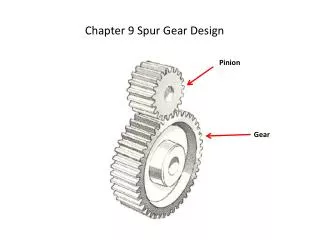
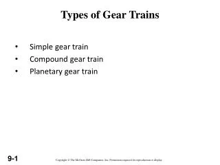
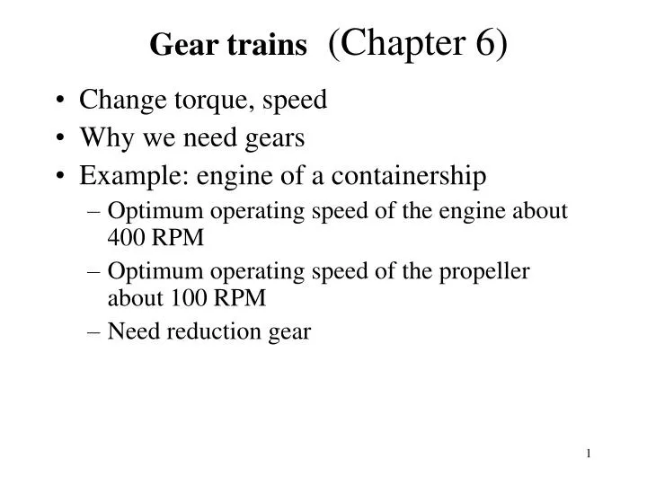
Gear trains (Chapter 6). Change torque, speed Why we need gears Example: engine of a containership Optimum operating speed of the engine about 400 RPM Optimum operating speed of the propeller about 100 RPM Need reduction gear . Connecting the main engine to the propeller

E N D
Gear trains (Chapter 6) • Change torque, speed • Why we need gears • Example: engine of a containership • Optimum operating speed of the engine about 400 RPM • Optimum operating speed of the propeller about 100 RPM • Need reduction gear
Connecting the main engine to the propeller through a reduction gear Output flange Propeller, operates at about 100 RPM Engine Gear Engine operates at about 400 RPM
Gear box Stick shift Synchronizers The gear box is in first gear, second gear
Important definitions • Velocity ratio=mV=angular velocity of output gear/ angular velocity of input gear=pitch diameter of input gear/pitch diameter of output gear • Torque ratio=mT=torque at output gear/torque at input gear • mT=1/mV • Gear ratio=mG=Ngear/Npinion,mG is almost always greater than one
Fundamental law of tooth gearing (6.2 and 6.3):velocity ratio must be constant as gears rotate Angular velocity ratio= ratio of distances of P from centers of rotation of input and output gear. If common normal were fixed then the velocity ratio would be constant. 2 T 3 3
If gear tooth profile is that of involute curve then fundamental law of gearing is satisfied Involute curve: path generated by a tracing point on a cord as the cord is unwrapped from base cylinder
Generating gear teeth profile • Steps: • Select base circles • Bring common normal AB • Draw involutes CD, EF P
Gear action Angular velocity of Gear 3 / angular Velocity of gear 2 = O2P/O3P = constant
Fundamental law of gearing:The common normal of the tooth profiles at all points within the mesh must always pass through a fixed point on the line of the centers called pitch point. Then the gearset’s velocity ratio will be constant through the mesh and be equal to the ratio of the gear radii.
Base circle radius = Pitch circle radius cos
Initial contact: B Final contact: C Path of approach: BP=ua=[(r3+a)2-rb32]1/2-r3sin Path of recess: PC=ur=[(r2+a)2-rb22]1/2-r2sin
Standard gears: American Association of Gear Manufacturers (AGMA) (6.4) Teeth of different gears have same profile as long as the angle of action and pitch is the same. Can use same tools to cut different gears. Faster and cheaper product. Follow standards unless there is a very good reasons not to do so.
AGMA Specifications • Diametral pitch, pd=1, 1.25, 1.5,…,120 • Addendum of pinion = addendum gear • Observations • The larger the pitch, the smaller the gear • The larger the angle of action: the larger the difference between the base and pitch circles, the steeper the tooth profile, the smaller the transmitted force.
Min: 0.25/pd 1/pd /pd 1.571/pd 1.25/pd d=N/pd 0.25/pd 0.3/pd
Planetary (or Epicyclic) Gears (10.4) • Gears whose centers can move • Used to achieve large speed reductions in compact space • Can achieve different reduction ratios by holding different combinations of gears fixed • Used in automatic transmissions of cars
Planet Carrier Input shaft Sun gear Ring gear Components of a planetary gear
A variant of a planetary gear Carrier
Planetary gears in automotive transmission Planetary gears
Velocity Analysis Of Planetary Gears (10.6, 10.7) • Two degrees of freedom • Given the velocities of two gears (e.g. sun and carrier) find velocities of other gears • Approach • Start from gear whose speed is given • Use equation gear = car+ gear/car