Download
1 / 34
340 likes | 557 Views
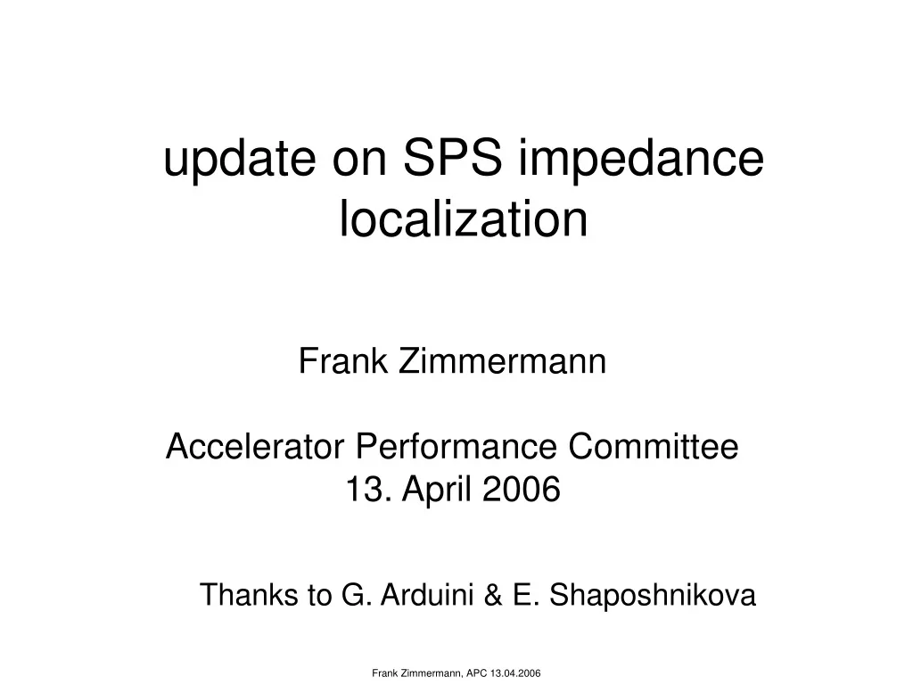
update on SPS impedance localization. Frank Zimmermann Accelerator Performance Committee 13. April 2006. Thanks to G. Arduini & E. Shaposhnikova. introduction reminder of results presented to the APC on 26. 05. 2005. Optics Perturbation. APC 26.05.2005.

E N D
update on SPS impedance localization Frank Zimmermann Accelerator Performance Committee 13. April 2006 Thanks to G. Arduini & E. Shaposhnikova
introductionreminder of results presented to the APC on 26. 05. 2005
Optics Perturbation APC 26.05.2005 considering only vertical plane, impedance acts like a current-dependent quadrupole of effective gradient bunch population effective impedance beam energy note that vertical impedance is defocusing
impedance will introduce beta & phase beating (C. Carli); explains oscillations in 2003 analysis APC 26.05.2005 response matrix was derived in 1st order perturbation theory: rewritten as adding 87x237 matrix cut-off of singular values in SVD inversion is another free parameter + SVD solution is stabilized by introducing additional equations with weights l M computed from MAD optics solution obtained by matrix pseudo-inversion, e.g., SVD
take data at different beam intensities Nb • for each BPM & data set, determine the phase of • oscillation with respect to the start of the line; constrain f to lie within +/-p from MAD model then for each BPM fit f vs. Nb to a straight line APC 26.05.2005 → apply previous equations to obtain DK/DNb from Df/DNb optics phase error at 0 current (?) effect of impedance
determine impedance sources at positions of 237 quadrupoles quads # 11, 24, 88, 102, 139, 164 (QD111, QDA119, QD307, QD319, QF420 and QD507) w. large impedance quads # 24, 80, 136, 140, 157, 164, 236 (QDA119, QD301, QDA417, QD421, QD501, QD507, and QD635) with large impedance • SVD minimization recipe: • singular-value cut-off = 5 • initial weight l = 1 for all quadrupoles; increased by factors of 10 for DK values of the wrong sign in 10 iterations, to make impedance defocusing APC 26.05.2005
current-dependent phase change predicted by biased SVD fit compared with the measurements fair agreement “perfect” agreement APC 26.05.2005 based on impedance distribution from previous slide
Robustness checks (1) selection of quadrupoles could impedance located near QD301 in reality be due to rf cavities (at quadrupoles 316-317)? [G. Arduini] • re-processed only 14 GeV/c data which have higher quality • successively eliminated quadrupoles in the 300s region with large fitted impedance from subsequent fits until rf cavity location is found QD301 QF300 QD305, QD309 QE302, QF308, QD313 QD317 QF304, QECD306, QF316, QD317, QD319 APC 26.05.2005
fit quality only slightly degrades as more and more quadrupoles are added APC 26.05.2005
fit with all quadrupoles fit without 9 quadrupoles in the 3rd arc APC 26.05.2005
results from full fit & from fit w/o 9 quads compared with data difference between the two fits is much smaller than the remaining discrepancy to the measurement APC 26.05.2005
(2) dependence on quadrupole weight effect on fit quality of varying initial quadrupole weight APC 26.05.2005
impedances fitted for different initial values of l l=0.01 l=0.1 APC 26.05.2005 l=1 l=10
fits for different initial l values and the measurement APC 26.05.2005
two outstanding actions (APC 26/05/2005, reminder GA 29.01.06): the available information on the transverse impedance from rf cavities (or others?) should be included in the model explore possibility that the impedance source in Sextant 5 is compatible with a localized source in 517 (instrumentation - IPM in particular)
rf impedance - knowledge meeting with Elena Shaposhnikova on 02.02.2006, providing two papers: T. Bohl/U. Wehrle, ‘RF Installations in the SPS’ updated 2006-01-25 T.P.R. Linnecar, E.N. Shaposhnikova, ‘Resonant Impedances in the SPS,’ SL-Note 96-49 RF TW 200 MHz, fr=938.5 MHz (V), R/Q=16.4 W, Q=1500, Ztotal=2.49 MW/m, 4 cavities, at locations 2832.32 m,2866.35 m, 2897.95 m, 2928.62 m TW 800 MHz, fr=1146 MHz, R/Q=335 W, Q=1000, Ztotal=4.0 MW/m, 2 cavities at locations 2843.80 m, 2854.87 m
Form of the transverse resonator impedance: RF Group seems to use following formula for the transverse broadband impedance: where Rs is in units of W [also Oliver Bruning, LHC-PN-36] Alex Chao’s textbook [also Francesco Ruggiero, CERN- SL-95-09; Bruno Zotter, LEP-TH/87-34] where Rs is in units of W/m2 SL Note 96-49 RF: travelling wave cavity standing wave cavity if I use these last relations which is the functional form of the impedance?
tentatively I now take transverse impedance Zt from SL note, but then I identify it with Zt in the expression derived from Alex’ textbook, and employ this latter formula for computing an effective impedance doing so I obtain: Zeff ~ -i 1685 W/m for 200-MHz system Zeff~ -i 4040 W/m for 800-MHz system these numbers are much smaller than total SPS transverse system Zeff~ -i 20 MW/m lowest mode is not sufficient to estimate effective impedance for a single bunch
summary 1: rf impedance two problems: • do not have any reasonable estimate for the broadband impedance, only data for 1 HOM • formula for transverse HOMs does not seem to comply with standard theory (Chao, Ruggiero,…) I cannot pursue this action further until these problems are resolved
(2) repeat previous analysis using different weights etc., in particular w.r.t. impedance of sector 5
normalize data differently to allow for direct comparison with result of coherent tune shift measurement current-dependent quadrupole strength is converted into effective impedance: = for 14 GeV/c & sz=0.3 m
potential impedance locations: MKQ: 1165-1167 MKD: 1173-1175 MKP: 11931-11955 MKE: 41631-41654 RF: 31637-31934 IPM: 4169? instrumentation: 517 …
all quadrupoles initial weight=1, SVD cutoff=5, l=10 fit quality: ((Df/DN)fit-(Df/DN)meas)r,s=0.00234 (2p/1011) rms impedance strength: 4.86x10⁻⁵ [m-1/1011] total impedance S b/<b> Im (Z) = 30.9 MW/m QDA11910 3.05 MW/m QD63510 1.97 MW/m QD30110 1.82 MW/m QD42110 1.75 MW/m QD50710 1.75 MW/m QDA41710 1.45 MW/m QD50110 1.15 MW/m QD10510 1.11 MW/m QD11510 0.89 MW/m QD13310 0.83 MW/m …
ImZeff [W/m] fit with all quadrupoles impedance weighted with b function QDA119 MKP? QD635,?? QD301, RF?? QD421, MKE? QD507, ?? QD105 QDA417, MKE? QD501, ?? QD115, MKQ? QD525, diagnostics QD133, ??
without 11 quadrupoles (w/o QD301, QF300, QD305, QD309, QE302, QF308, QD313, QF304, QECD306, QD501, QD507),initial weight=1, SVD cutoff=5, l=10 fit quality: ((Df/DN)fit-(Df/DN)meas)r,s=0.00255 (2p/1011) rms impedance strength: 4.63x10⁻⁵ [m-1/1011] total impedance S b/<b> Im (Z) = 29.5 MW/m QDA11910 3.24 MW/m QD42110 1.60 MW/m QD31710 1.49 MW/m QD10310 1.49 MW/m QDA41710 1.46 MW/m QD11510 1.08 MW/m QD52510 0.86 MW/m …
fit without 11 quadrupoles: QD301, QF300, QD305, QD309, QE302, QF308, QD313, QF304, QECD306, QD501, QD507
fit without 11 quadrupoles: QD301, QF300, QD305, QD309, QE302, QF308, QD313, QF304, QECD306, QD501, QD507 ImZeff [W/m] QDA119 MKP? QD317, RF? QD421, MKE? QD103 QDA417, MKE? QD115, MKQ? QD525, diagnostics
another fitting attempt consider all ‘H/V kicker’ and ‘rf cavity’ elements as potential impedance sources instead of the quadrupoles; there are 308 such elements in the SPS MAD model
with kickers and rf cavitiesinitial weight=1, SVD cutoff=5, l=10 fit quality: ((Df/DN)fit-(Df/DN)meas)r,s=0.00236 (2p/1011) rms impedance strength: 3.95x10⁻⁵ [m-1/1011] total impedance S b/<b> Im (Z) = 29.4 MW/m MDV50907 2.24 MW/m MDV30107 1.47 MW/m MDV10307 1.31 MW/m MDVA11904 1.24 MW/m MKP11931 1.09 MW/m MDV42307 0.84 MW/m
ImZeff [W/m] fit with all kickers and rf cavities (no quadrupoles) MDV509 MDV103 MDV301 MDVA119 MKP119 MDV423
summary 2: new fitting studies large impedances are consistently found at the following five locations (both when fitting to quadrupoles and to kickers/rf): 103-105 119 (MKP?) 301 (→317(RF?) w 9 quads suppressed) 417-423 (MKE?) 501-509 (disappears if quads 501&507 are removed from the fit) accurate optics model is essential!