Download
1 / 57
630 likes | 1.01k Views
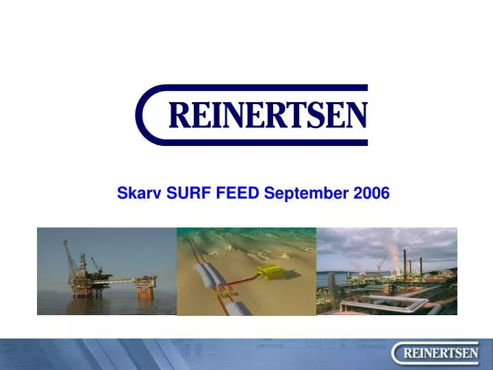
Skarv SURF FEED September 2006. Reinertsen’s role in Skarv : Early part of FEED (Front End Engineering and Design ) two main contributors : FPSO ”Everything below the surface”. Organisasjon. REINERTSEN AS. Erik R./Torkild R. Reinertsen (50/50%). STØTTEFUNKSJONER.

E N D
Reinertsen’s role in Skarv : Early part of FEED (Front End Engineering and Design ) two main contributors : FPSO ”Everything below the surface”
Organisasjon REINERTSEN AS Erik R./Torkild R. Reinertsen (50/50%) STØTTEFUNKSJONER (HMS/KS, IT, Økonomi, Personal, Forretningsutvikling) * STORE PROSJEKTER Divisjon Divisjon Divisjon Divisjon INSTALLASJON ENTREPRENØR ENGINEERING FABRIKASJON Trondheim, Oslo og Bodø Orkanger Trondheim og Bergen Trondheim, Oslo og Bergen REINERTSEN AB REINERTSEN NWR AkerReinertsen AS Stockholm og Gøteborg Murmansk, Russland Trondheim Selberg Arkitektkontor AS (75%) Trondheim ConSepT AS (51%) Trondheim Omsetning : 2 000 mill kr Antall ansatte : 1 300 * EPCI og Entrepriseprosjekter
Flerfaglig Engineering Total engineering 550 • Prosjektledelse 50 • Prosess 35 • Instr/Elektro 60 • Rør / Mekanisk / HVAC 90 • Struktur / Stål 65 • Teknisk sikkerhet 15 • Prosjektstyring 50 • Anskaffelser 30 • Rørledninger 55 • Bygg / samferdsel 100
Divisjon fabrikasjon, avd. Orkanger • Startet 1996 • Tomteareal: 60.000 m2 • Fabrikasjonshaller: 3.640 m2 • Kontorer: 1.350 • Utfører fabrikasjons-/sammenstillingsfasen i O&G prosjektene til REINERTSEN • Utfører tjenester innen rør, plate, sveis, NDT/TT, dim.kontroll, overfaltebehandling (underlev.)
NORNE SUBSEA TEE PROTECTION STRUCTURES Y-CONNECTIONS FOR PIPELINES Skirne / Byggve kompressormodul
Divisjon fabrikasjon, avd. Murmansk (”REINERTSEN NWR”) • Strategisk viktig etablering med tanke på økt konkurransekraft, så vel som posisjonering ovenfor ett spennende marked som kommer. • Etablering av verksted for prefab av stålkonstruksjoner • Norsk ledelse, russiske operatører • Opplæring og sertifisering på Orkanger • Utstyr importert hovedsaklig fra Norge (!)
Kollsnes Tjeldbergodden
PIPELINE EXPERIENCE • REINERTSEN Engineering has performed engineering of subsea pipelines for more than 20 years. • Detail Engineering projects: 45 • Engineering Studies, Basic Engineering and Verification projects: 70 • Ongoing Detail Engineering projects: • Ormen Lange pipelines • Snøhvit pipelines • Marlim, Golfinho - Brasil
Skarv is Technically interesting, as RE does the FEED of all main parts subsea : Risers, flowlines, export line, umbilical, manifolds, tie-ins, templates (FMC Kongsberg under RE) • Production Facility Characteristics: • Reserves 420 Mboe • Oil production capacity 85 Kbopd • Gas production capacity 670 mmscf/d • Gas export capacity 500 mmscf/d • Gas injection capabity 250 mmscf/d • SURF/Export Scope (Phase 1): • 400 m water depth • 4 Subsea Drill Centres • 16 Wells (13 pre-drilled) • 80kms of 26” spur pipeline to ÅTS line • Environmentally sensitive seabed (corals)
Main concept for the Skarv project Note : Some of the wall thicknesses may be outdated
5 drill centres tied back to one FPSO : Skarv A : Gas production Skarv B/C, Template 1 (West) : Oil production, water injection Skarv B/C, Template 2 (East) : Oil production, gas injection Tilje : Oil production, gas injection Idun : Gas production In addition there is a possible, future template, to be installed around 2018 : Snadd S : Gas production Anticipated field life is 25 years. Export of production oil and condensate will be by shuttle tanker. Gas export will be via a dedicated export pipeline to the Åsgard Transport System.
Packages procured as part of RE scope : Pipe supply, flowlines ITT 2006/2007 Pipe supply, GEP ITT 2006 Flowline installation ITT 2006 Gas Export pipeline installation ITT 2006 Riser supply ITT issued Riser installation ITT 2006/2007 GEP coating ITT 2007 Umbilical supply ITT 2007 General subsea installation ITT 2006 Subsea production system (SPS) ITT Sept./Oct 2006 Valve supply ITT 2007 Connector supply ITT 2007 Fabrication of structures ITT 2007 ITT = Invitation to Tender
BP will handle bids. Thus, no particular strategy towards tenderers from RE’s side. RE’s scope is merely assisting BP with ITT preparation, evaluation of tenders and giving advice in technical questions.
Natural to split between flowlines and the gas export line : Flowlines : 10” and 12” pipelines, mostly 2 to 5 km long. Max. is Idun of 12km. Riser bases may move (probably) No SSIVs Template at far end Gas export line : 26” pipeline, 80km long Fixed export riser base 2 SSIVs Tie-in to existing Åsgard Transp. T
Flowline system, Risers ITT’s for riser supply already issued Riser vendor will probably deliver the risers with bending stiffeners included. Vendor to be decided arround December this year.
Flowline system, Risers The riser system consists of 11 risers and 2 dynamic umbilicals. The risers are un-insulated 8” and 10” production risers, as well as 12” gas injection and gas export risers. Pipelines will be connected to the riser system at the riser bases located approx. 350 m.
Flowline system, Risers Perhaps a market for rock dumping, concrete mats on the seabed, anchoring, buoyancy elements or installation. Otherwise not much for local suppliers.
Flowline system, riser bases (RB) Riser base (10” & 12”) 9 riser bases (plus one for Snadd) Dimensions: 9.5m x 3.3m Dry weight: 20 tonnes
Flowline system, riser bases (RB) Procurement items : Material supply Valve supply Fabrication Design parameters : 9 riser bases Will move on the seabed (probably) Pdesign = 330 bar or 420 bar (GI) Tmax = 135oC or 60oC (GI) Tmin = - 30oC or -10oC (GI) 10” or 12” Flowlines (clad steel) 8” or 10” Risers
Flowline system, Pipelines Different layout options have been evaluated for the flowlines. At the FEED phase BP has landed on one base case and three optional solutions. Base case for the flowlines is the following : 1) Skarv A,Skarv B/C and Tilje clad steel piping + 25% Cr. (in Zone 2). Wet insulation (U value = 3 W/m2K), Reeled. 2) Idun with Butting Bubipipe (?). Wet insulation (U value = 3).S-Laid, Hydrate management through DEH, Direct Electric Heating (long line) Maximum possible wall thickness (from fabrication point of view) will be used, i.e. 18mm for 10" lines and 22mm for 12" lines in Zone 1.
Skarv Flow Lines, Piping 3 alternative solutions for the flowlines are : 1) All flowlines reeled with 13% Cr. Material. 2) All flowlines laid in bundles. 3) Combined bundle (Skarv A, B and C) and S-Lay (Idun)option
Flowline system, Pipelines Possible supply items : Seabed intervention Counteracts Installation of pipe Input parameters : Rugged terrain with Ploughmarks from the Ice Age Volume of stone dumping up to 120 000 m3 for the flowlines(crude estimate = 3m3 pr. m. pipeline. Kristin was by comparison 0.4m3) Export line = 240 000m3 Total = 2.3 x Oslo Rådhus Depth up to 400 m. 2.3 x
Estimated Number of Tie-Ins Base case
Flowline system, Pipelines Possible supply items : Pipeline insulation Input parameters : U=3 W/m2K Multilayer PP coating with FBE layer inside.
Flowline system, Pipeline End Terminations (PLET) PLET STRUCTURE 9 PLETS for the flowlines (plus one for Snadd) SIZE 2.3 m x 5.3 m x 1.8 m (W, L, H) DRY WEIGHT Approx. 3 Tonnes
Procurement items : Material supply Fabrication of structure Connector Design parameters : 9 PLETs Pdesign = 330 bar or 420 bar (GI) Tmax = 135oC or 60oC (GI) Tmin = - 30oC or -10oC (GI) 10” or 12” Flowlines (clad steel)
Flowline system, Spools • Spools will probably be of clad steel piping from JSW. Procurement items : Fabrication Design parameters : 9 spools Pdesign = 330 bar or 420 bar (GI) Tmax = 135oC or 60oC (GI) Tmin = - 30oC or -10oC (GI) 10” or 12” Flowlines (clad steel) • (3D ANALYSES MODEL • Nonlinear Analyses including nonlinear material behaviour and friction against seabed. PLET included in analyses model )
Spool Weights and Maximum Sizes • Spools sizes governed by analyses, installation tolerances and required clearance to nearby spools/structures • For 12” the biggest spools are between Skarv A/Tilje Templates. Size governed by template locations.
Flowline system, Templates Templates will be given as a complete EPC contract. Common suppliers are : FMC Kongsberg Aker Kværner Subsea Vetco (previous ABB) Cameron Drillquip
Flowline system, Templates A number of items to be supplied for each of the 5 templates : Steel work Xmas trees Valves Couplings / control systems Multiphase metres Electric connectors Pressure/temperature sensors Choke bridges However, to be procured by EPC contractor (contract award around 1st. Of April)
Umbilicals Procurement items : Manufacturing of umbilical Installation of UMB Bending stiffeners, buoyancy elements Challenge : Big ! 220-270 mm. cross section Weight=30-50 kg. pr. meter 24 hydraulic lines 20 el. subsea connectors Several subsea optical connectors 1.5” pipes, prone to fatigue Total length of at least 22 km.
Umbilicals URB Dimensions: 11m x 6m (HOLD) Dry weight: 35 tonnes (HOLD)
Umbilicals Procurement items : Procurement items : Procurement items : Material supply Fabrication Installation Design parameters : Design parameters : Design parameters : 350 meters depth Challenge : Big termination head as well : Weight = 4-5 tons Dia = 5-700 mm. Length = 5-6 m. Another challenge is to avoid conflict between the flexible umbilicals and the other risers
Gas export line system : Some components similar to those of the flowlines, but…
Export riser base (ERB) : Procurement items : Procurement items : Procurement items : Material supply Valve supply Fabrication Design parameters : Design parameters : Design parameters : 1 ERB Fixed on seabed Pdesign = 303 bar Tmax = 60oC Tmin = - 10oC 26” normal Carbon steel pipeline 22.5 mm. Wall thickness in pipeline
GEP, Pipeline : Procurement items : Seabed intervention Counteracts Insulation installation Design parameters : 80 km of 26” normal carbon steel pipeline 3 layer polyethylene coating and 45 mm. layer of concrete PE coating inside pipeline to optimize flow, corrosion protection during storage and to ease cleaning Pdesign = 240 bar Tmax = 60oC Tmin = - 10oC Pipeline will be S layed. Intervention work will mostly consist of stone dumping for reduction of free spans and expansion control. 240 000 m3 of rock estimated.