Download
1 / 43
430 likes | 441 Views
Heavy Ion Simulation Tools in ATLAS. Pavel Nevski BNL Motivation Simulation Dataflow Event Characteristics Subsystems Performance. Heavy Ion Physics with ATLAS Detector. ATLAS interest in heavy ion physics was activated by highlights from RHIC experiments!.

E N D
Heavy Ion Simulation Tools in ATLAS Pavel Nevski BNL Motivation Simulation Dataflow Event Characteristics Subsystems Performance
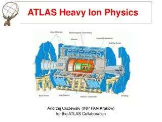
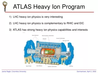
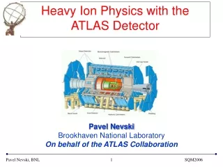
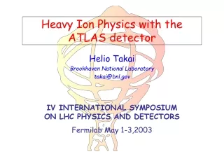
Heavy Ion Physics with ATLAS Detector ATLAS interest in heavy ion physics was activated by highlights fromRHIC experiments! Hot/dense Nuclear Matter Diagnostics • Suppression of high pT particles • Disappearance of back-to-back high pT jet correlations • Huge azimuthal asymmetry at high pT ATLAS is an excellent detector for high pT physics and jet studies
ATLAS as a Heavy Ion Detector • High Resolution Calorimeters • Hermetic coverage up to || < 4.9 • Fine granularity (with longitudinal segmentation) High pT probes • Large Acceptance Muon Spectrometer • Coverage up to || < 2.7 Muons from , J/, Z0 decays • Si Tracker • Large coverage up to || < 2.5 • Finely segmented pixel and strip detectors • Good momentum resolution Tracking particles with pT 1.0 GeV/c Heavy quarks(b), quarkonium suppression(, ’) 2.+ 3. 1.& 3. Global event characterization
Simulation DataFlow Hijing Geometry +Tracking - ATLSIM(G3) +ROOT Event Mixing +Digitization - +ATLSIM(G3) +ROOT Reconstruction - +ATLSIM(G3) +ROOT Analysis - +ATLSIM(G3) +ROOT Pythia Mickey-Mouse Generator Single Particle gun Output: Event in Memory or as Zebra, Ntuple,Root or ASCII file Output: Hits in Memory or Zebra File Output: Signals (Digits) in Memory or Zebra File Output: Reco Objects in Memory or Zebra File
Simulation Tools: Generators HIJING Event Generator: Based on PYTHIA and Lund fragmentation scheme (Soft string dynamics + hard pQCD interactions) with nuclear effects:nuclear shadowing,jet quenching Pb+Pb b=0 fm sNN=5.5 TeV quenching, no shadowing quenching, shadowing no quenching, shadowing
Central Event Multiplicity All particles output by HIJING event generator – stable plus their parents 100 events generated
Stable Particles after HIJING Per 10 Events All decays faster then pi0 are now done by hijing, But you can switch some of them off
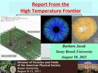
Simulation view- E vs Rapidity Particles at high rapidities transport enormous energies but have little impact on detector We use rapidity cut at +/- 3 units in this simulations
Few Numbers at a Glance • More then 30 millions distinct volume copies • 25 thousand different volume objects • 7 thousand different volume types • Only 33 K lines of code (with digitization!) • No step routine is needed for most of the detectors, no “if statement” problem • Few hundred pile-up events possible • About 1 million hits per event on average
Software Challenge • Few basic numbers in an engineering description (about 1200 in ATLAS). • Complicate relationship between input numbers and geometry objects (drawings). • More “readers” than “writers”, not all of them are software engineers. • A lot of geometry objects in the final model (30M in ATLAS), a lot of code at the end. • Maintenance over dozens of years.
Dice95 (Atlsim) • Third generation of the ATLAS simulations tools • Strictly hierarchical design to separate detector specific code from the infrastructure • Stable GEANT3 simulation framework since 95 • Improved memory management • Elastic ZEBRA (using malloc) • No limits on number of tracks, vertices, hits etc (apart from physical memory limits) • Interfaces to existing and future services • Geant3/paw, MySQL … ROOT and even more
Dice-95: Functionality in Term of Layers • Layers a la Open System Interconnection (OSI) model: • “External – parameter database • “User” – generic geometry description • “System” – object generation interface • “Application” – Geant 3/4, reconstruction, root • “Low” (logical) layer – ZEBRA, root, LHC++ • “Basic” (physical) layer - platform dependant code, system libraries,graphics etc
Geometry Description • For geometry description a specificationlanguage is a must ! • Detectors have parameters which may describe geometry evolution. • Most of the geometry dimensions has to be calculated using parameters. • Both input parameters and calculation results should be available to the reconstruction. • A mechanism of keeping both parameters and calculation results is needed. • What should it be if we don’t want to write a new language ? any existing …+ more !
Geometry Specification • Role of the geometry specification. • Use simplest possible tools to pass user’s perception of geometry objects to an executable code. • Creates instances of a “user request” objects and invokes a generic object constructor (material, volume, rotation matrix etc). • Actual object creation is completely decoupled from the geometry description language and done by the generic constructor.
Generic Constructor • It gets and executes a single “user request.” • It takes care of bookkeeping: • If an object with requested attributes already exists, return pointer to it. • If object attributes are different from all previously existing objects, a new object is created and its pointer is returned. • Output is similar to “flat XML” apart from • maintenability • Generic and symmetry memory • This is where the most of the coding happens.
Database Interface • Loading geometry data or opening an existing configuration creates a relational database in memory - a subset of the full database. • Selection of an actual copy of each structure (instantiation) is done by the use statements. • Any variable from the structure can be used as a selection key – within selected configuration. • USE processor in AGI makes dynamic brokerage in case the structures in the code differs from DB.
ATLAS Parameter Database • Contains only independent (basic) parameters • Parameter values: ~14,000 • Dimensions and positions are calculated in the code
Resulting G3 Geometry Model • Complete geometry model is created only in the computer memory as a result of code execution with a set of input parameters coming from: • Default code versions • Database (MySQL supported) • Data card parameters and version input • Selection is done at run-time (user controlled) • Resulting geometry is persistent, as well as all selected input parameter structures
Generic Geometry Via ROOT TDataset TVolumePosition TGeant TVolume TVolumeView ctor ctor TNode TVolumeView TShape TVolumePosition list
Hit Service: Definitions Universal hit definition: HITS volume measurement:bin_or_bits:(a,b)... • A hit is a container of measurements, representing a piece of particle trajectory. • Most of the measurementsare similar for all detectors and rather trivial: • X,y,z – local or global, momentum and directions. • eta or phi, time of flight, deposited energy. • Distance of the closest approach to a wire. • Repeating their coding was error-prone.
Hit Service: Mixing and Sorting • Universal hit sorting => see demo at three. • Hits are produced along a particle trajectory, but most often are analyzed together in a detector element. • Hits are often produced in different events, but still analyzed together in the same detector element. • A flexible hit navigation may solve both tasks. • It also can be detector independent.
Hit Service: History • It is often desirable to determine the origin of a hits from secondary tracks, produced during simulations. However in practice it is hard to save all secondary tracks. • DICE can save only those secondaries, which have produced a hit in specified detectors or made a specified interaction. • The vertex entry of secondary tracks keeps their closest ancestor as well as the originating process and volume where it happened.
Hit Service: ROOT Access class TPoints3DABC (from ROOT G3D) GZEBRA TGeantHits3D TGeantHits() ... GetNextHit(Int_t indx) aghitset() aghitget()
Central Pb+Pb Collision Nch(|y|0.5) • About 75,000 stable particles • ~ 40,000 particles in || 3 • CPU – 6 h per central event (800MHz) • Event size 50MB (without TRT)
Simulated Event Samples HIJING + full GEANT3 ATLAS detector simulations Only particles within |y| < 3.2 • High Geant thresholds 1 MeV tracking/10 MeV production • 5,000 events in each of 5 impact parameter bins: • b = 0-1, 1-3, 3-6, 6-10, 10-15 fm • Standard ATLAS thresholds 100 keV tracking/1 MeV production • 1,000 central events, b = 0-1fm • Initial layout – 2 pixel barrel layers • 1,000 central events, b = 0-1fm
Event Reconstruction • Most of the standard ATLAS reconstruction packages are working on HI events after minimal parameter tuning • We have successfully exercised all calorimeter reconstruction - photons, jets, missing energy. Of course, jet reconstruction is a tricky issue - work is ongoing to develop an appropriate code • Silicon Pixel and Strip detectors have reasonable occupancy and can provide track reconstruction • Muon reconstruction is even simpler in HI events - provided the muon energy is above 6 GeV
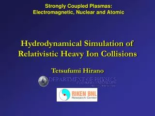
Pixel occupancy vs. rapidity • Average occupancy close to one per cent • Strong local fluctuations • Outermost layers are in a better condition • 4096 pixel limit in the readout system -corresponds to 4% maximum occupancy
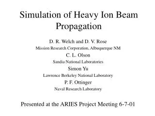
Strip occupancy vs. rapidity • Occupancy is significantly lower in the outermost layer • Even in worse case still below 20 per cent
Track Reconstruction Track reconstruction performed with ATLAS pp tracking code using the Pixel and SCT detectors (xKalman++). • pT threshold for reconstructable • tracks is 1 GeV. • Tracking cuts are optimized to • get a decent efficiency and • low rate of fake tracks. For pT 1 to 15 GeV/c: efficiency ~ 70 % fake rate 10% Eff. ~80% , fake rate 15-20% Eff. ~65%, fake rate ~5%
Track Reconstruction Efficiency versus rapidity Momentum resolution Flat dependency for |y| < 2 ~3% for pT up to 20 GeV/c
B-jet Tagging • Preliminary study: • Standard ATLAS algorithm for pp • Higgs events embedded into pp or Pb-Pb event • Cuts on the vertex impact parameter in the Pixel and SCT Rejection factors against light quarks versus b-tagging efficiency p-p Pb-Pb Promising, should be improved when combined with muon tagging!
Calorimetry Energy Per Cell: • 0.025 x 0.025 cell in e.m. calorimeter • 0.10 x 0.10 cell in hadron calorimeter
Jets and Clusters • Reconstructed e.m. clusters – exotic processes can be observed with cluster energy more than ~15 GeV (?) • Reconstructed hadronic jets – jet signature can be used with Pt above 50 GeV (?)
Quarkonium Suppression Direct probe of the QGP: Color screening of the binding potential leads to the dissociation of the quarkonium states. Upsilon family(1s) (2s) (3s) Binding energies (GeV) 1.1 0.54 0.2 Dissociation at the temperature ~2.5Tc ~0.9Tc ~0.7Tc Important to separate (1s) and (2s) +– Upsilon mass reconstruction using the Muon Spectrometer, Silicon Tracker and the Pixel Detector.
Muons • Energy of muons which have reached the muon system (about 5-6 GeV are lost in the calorimeter) • Reconstructed muon energy (not corrected for energy loss in calorimeter)
Quarkonium Suppression • GEANT3 simulations of pure (1s) and (2s) states +– • Muons with pT > 3GeV are tracked backwards to the ID • Invariant mass is calculated from the overall fit. =130MeV • Background estimate (HIJING+G3) S/B ~ 0.6 • Acceptance 10-15% providing 100% efficient dimuon trigger • Overlay with HIJING Event is under study!
Trigger DAQ For Pb+Pb collisions the interaction rate is 8kHz, a factor of 10 smaller than LVL 1 bandwidth. We expect further reduction to 1kHz by requiring central collisions and pre-scaled minimum bias events (or high pT jets or muons). The event size for a central collision is ~ 5 Mbytes. Similar bandwidth to storage as pp at design L implies that we can afford ~ 50 Hz data recording.
Conclusion • ATLAS detector will be capable of measuring many aspects of relatively low pT heavy-ion physics • Simulation, Reconstruction and Analysis tools exist to evaluate the detector performance • Work is in progress to understand the detector performance for studying the truly high pT phenomena