Download
1 / 28
300 likes | 462 Views
Servo Motor Control. Demonstration. homing switch. limit switch. motor with gear reducer. flex coupling. incremental optical encoder. Closed-Loop Control. How does the computer do this?. computer controls the current going to the motor. motor. gear reducer. desired steering angle

E N D
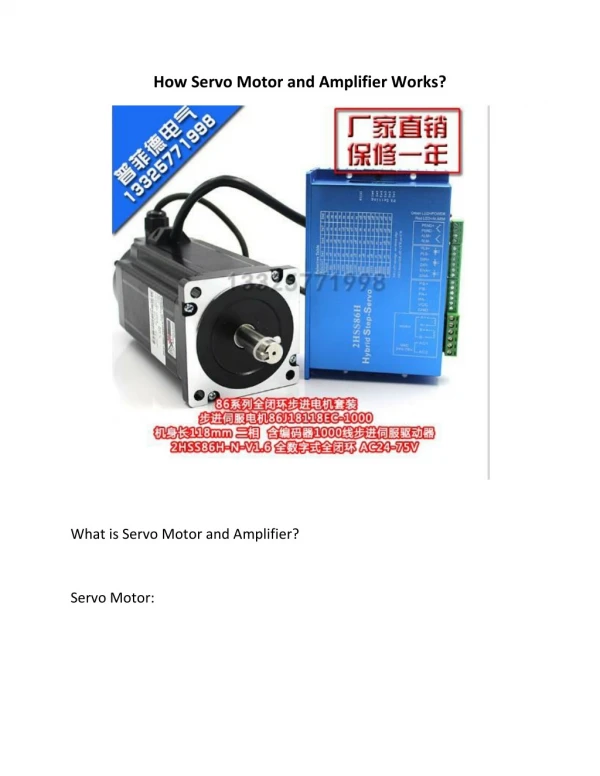
Servo Motor Control Demonstration
homing switch limit switch motor with gear reducer flex coupling incremental optical encoder
Closed-Loop Control How does the computer do this? computer controls the current going to the motor motor gear reducer desired steering angle compared to current steering angle gear reducer and flex couplings (if needed) connect motor to steering shaft incremental optical encoder (with homing switch to initialize position) feeds back current motor position How does the computer ‘read’ the encoder information?
Interface to Computer • We will use a National Instruments USB-6009 data acquisition (DAQ) device • specs • USB interface to PC • 8 channels of analog input, 0-5V • 2 channels of analog output 0-5V5 mA each • 12 channels of digital input/outputs0 or 5V, (8.5 mA for outputs) • 1 counter
Honeywell / Clarostat 600128CN1 Allied Electronics part # 753-0059 cost: $41.67
Computer Interface • Let’s start with digital inputs to interface to the optical encoder. notice that there are four wires
channels A & B will be either 0V or 5V depending on whether that light detector detects light through a slit or not ground channel A channel B +5V power
ground channel A channel B +5V power
Closed-Loop Control How does the computer do this? computer controls the current going to the motor motor gear reducer desired steering angle compared to current steering angle gear reducer and flex couplings (if needed) connect motor to steering shaft incremental optical encoder (with homing switch to initialize position) feeds back current motor position
Computer Interface to Motor • To control the motor: • the computer must be able to generate an analog voltage signal • however, the typical analog voltage signal that a computer generates does not have sufficient current to power the motor • an amplifier is used • a power supply provides 24V (7.5 amp max for our case) to the amp • the computer generates an analog voltage in the range of-0 to +5V; 0V means the motor is to stop ; +5V means the motor is to turn at a maximum speed • a digital signal will give the desired direction (0 V, CCW, 5 V CW)
Change motor direction To go CW, set this digital output pin to TRUE (+5V). To go CCW, set this digital output pin to FALSE (0V).
Homing Switch 0V +5V to input pin on USB DAQ
Interface to Computer 0V from USB-6009 +5V from USB-6009
digital signal E stop switch input power analog signal computer controls the current going to the motor USB connection desired steering angle compared to current steering angle gear reducer and flex couplings (if needed) connect motor to steering shaft USB connection incremental optical encoder (with homing switch to initialize position) feeds back current motor position digital signal homing switch 2 digital signals
Design Project • If you decide to use a servo motor in your design: • include an optical encoder for motor position feedback • include a homing switch to initialize your position • include E-stop switches as needed