Download

1 / 19
410 likes | 1.41k Views
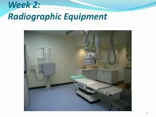
Mobile Radiographic Equipment. Introduction. In-patients who could not leave their beds Surgeons who required x-ray control guidance during the course of their work in the operation theatre. The basic design for a mobile unit. A wheeled base Built in X-ray generator Control panel

E N D
Introduction • In-patients who could not leave their beds • Surgeons who required x-ray control guidance during the course of their work in the operation theatre
The basic design for a mobile unit • A wheeled base • Built in X-ray generator • Control panel • Supported X-ray tube
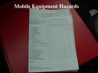
Some of the general rules • The exposure hand-switch cable must be at least 2 m long to allow radiographer to stand distant from irradiated patient • Lead protection must be used for personnel notinvolved with the examination • Protect other staff not involve with the examination
Electrical energy source • Directly from the mains voltage supply in this case static generator is installed permanently • A Capacitor can be charged from the mains voltage to the required potential difference and discharged through the x-ray tube • Battery design, which can provide the energy required by an x-ray generator
Main-dependant mobile equipment • The mains voltage supply must have robust connection cable • That cable encloses three low resistance conductors • Two of the conductors carry the current which the generator draws when an exposure is made • The third provide a safe, reliable connection to earth
Main-dependant mobile equipment • The cable must be long enough for the equipment to be used in most locations • Should provide a convenient mains outlet socket • The cable must be wound onto a wheel-type storage drum built into the equipment, when not in use to protecting it from physical damage • Using extension cable is not recommended
Extra length of cable will cause:1- Drop of voltage which may occur during an exposure2- Earth connection will be weak, that will reduce the safetyof the equipmentConventional generatorsX-ray generator is commonly about 30 A and may be higher
Capacitor discharge equipment • The main advantage is producing X-rays from the energy stored in and discharged from a capacitor • Main voltage and resistance variations only have their effects upon the act of charging the capacitor • When exposure is required the radiographer select the values of kVp and mAs. • The switch is then operated to charge the capacitor to the required kilovoltage via the high tension generator
Capacitor discharge equipment • The X-ray exposure involves first disconnecting the capacitor from the high-tension supply and then connecting it cross the X-ray tube • A special X-ray tube is required which incorporates a third electrode (grid) interposed between cathode and anode which is at a high negative potential (bias) • The effect of negative bias is to prevent filament electrons from crossing to the anode
Capacitor discharge equipment • When the exposure begins the negative bias is removed and it end when the bias is re-imposed • At the end of the time exposure when required mAs has crossed the tube, the negative grid (bias) is re-imposed to prevent further conduction • mAs = mC • The capacitance of the capacitor its ability to store electric charge and that measured as a ratio between the charge stored on the plates and the potential difference between them
Capacitor discharge equipment • The unit is farad = 1 coulomb per volt • In a mobile unit the capacitor employed usually has capacitance of 1 microfarad that can create 1 kV cross it • When discharge the potential difference falls of 1 kV for every mC i.e. every mAs • e.g. 90 kV and 20 mAs results in a final potential difference across the tube of 70 kV • If a large mAs is selected the kVp used should be low
Battery-powered generators • Provide correct, regular charging procedures • The direct voltage output has to converted into an alternating voltage, so that it can be transformed into a kV • Then followed by rectification • Batteries maybe nickel-cadmium or more conventional lead-acid type
Battery-powered generators • All batteries are sealed for safety • Charging is achieved by connecting the generator to a mains voltage supply at times when it is not required for radiography • Security is essential
X-ray tubes- The anode is rotating and sometimes is in a high speed- Some x-ray tube require a low voltage- The capacitor discharge equipment units have x-ray tubes which incorporate a grid to switch exposures- X-ray tubes are invariably fitted with LBD (Light Beam Diaphragm)- Scales and angle indicators are fitted to guide radiographers- The x-ray tube is delicate and expensive component of a mobile equipment unit. It is essential to protected against physical damage
Physical feature • The wheels are fitted with tyres made from antistatic rubber for safety • Motor is installed in some mobile equipment unit • Brakes and locks to slow down and immobilization • The tube support- Security
Special technical factor selection consideration- Kilovoltage it produce different from the stationary equipment- mAs the low power unit not capable of the high mAs and use high kVp instead to obtain sufficient density- The distance, should be estimated within 15% to avoid producing a visible density difference- The grid problem is proper alignment, low grids ratio 5:1 or 6:1 are often preferredand parallel instead of focused grid