Download
1 / 32
320 likes | 490 Views
Interferometer design of LCGT. Masaki Ando Department of Physics, University of Tokyo the LCGT collaboration. Outline. 1. LCGT interferometer overview 2. LCGT optical layout 3. Main interferometer design 4. Input and output optics 5. Observation system 6. Summary.

E N D
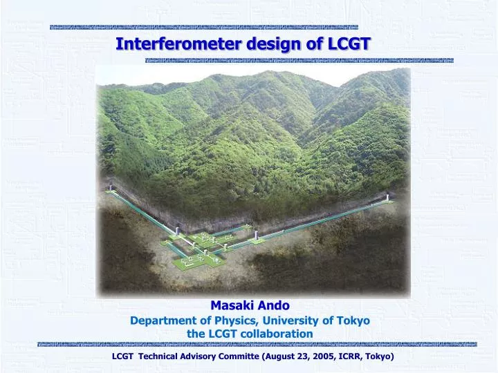
Interferometer design of LCGT Masaki Ando Department of Physics, University of Tokyo the LCGT collaboration LCGT Technical Advisory Committe (August 23, 2005, ICRR, Tokyo)
Outline 1. LCGT interferometer overview 2. LCGT optical layout 3. Main interferometer design 4. Input and output optics 5. Observation system 6. Summary LCGT Technical Advisory Committe (August 23, 2005, ICRR, Tokyo)
Interferometer overview LCGT Technical Advisory Committe (August 23, 2005, ICRR, Tokyo)
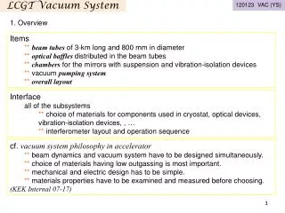
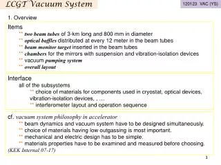
Overview (1) • Interferometer overview Input optics Two mode cleaners Baseline lengths : 10m and 180m Modulators for IFO control Laser stabilization Two nearby interferometers As independent as possible Center rooms: separated 3km vacuum tube: common Output optics Main interferometer Output mode cleaner Round trip length : 70mm Multiple InGaAs photo diodes Broad band RSE with power recycling Arm cavity Finesse : 1550 Power Recycling Gain : 11 Signal band Gain : 15 Stored Power : 771kW Signal band : 230Hz Observation system Monitor and organize the whole detector system Automatic lock-acquisition Automatic interferometer adjustment Monitor and diagnosis LCGT Technical Advisory Committe (August 23, 2005, ICRR, Tokyo)
Overview (2) • LCGT interferometer Main IFO : 3km IFO Input optics : Two MCs, Modulators, MMT Output optics: OMC, Photo detectors LCGT Technical Advisory Committe (August 23, 2005, ICRR, Tokyo)
Interferometer layout LCGT Technical Advisory Committe (August 23, 2005, ICRR, Tokyo)
Interferometer layout (1) • Layout of two interferometers 3km arm Center room for IFO-2 Center room for IFO-1 3km arm LCGT Technical Advisory Committe (August 23, 2005, ICRR, Tokyo)
Interferometer layout (2) • Optical layout of two interferometers Two interferometers are placed in separated center rooms make them as independent as possible 3km vacuum tubes are used commonly by two IFOs Combined at steering tanks Vacuum tube diameter: 1000 mm Beam separation: 600 mm Each main mirror is placed in an independent vacuum tanks Mirrors are separated ~30m Should be careful on Cross-coupling between interferometers Scattered-light from vacuum tube LCGT Technical Advisory Committe (August 23, 2005, ICRR, Tokyo)
Baffle Interferometer layout (3) Cross-coupling estimation Case1 Refraction- Scattering Refraction D Scatter Scatter Case2 Scattering- Scattering D Scatter 1ppm scattering Cross-coupling < 10-10 Scattered-light noise Scattered-light noise: Scattered-light on mirror surface reflected by inner surface of the vacuum tube Vacuum tube is shaken by seismic motion Re-enter to the main beam by scattering Vacuum tube Two-reflection case Mirror Mirror Reduced by baffles in the vacuum tube One-reflection case LCGT Technical Advisory Committe (August 23, 2005, ICRR, Tokyo)
Interferometer layout (3) Baffle for LCGT Specification of LCGT Tube diameter 1000mm Mirror diameter 250mm Mirror distance 600mm Mirror offset 340mm - 11 1/2 Seismic motion 1 x 10 m/Hz @30Hz Estimated scattered light noise - 21 1/2 4.2 x 10 m/Hz @30Hz (Safety factor=7) ( for one mirror) Baffle design 1/10 Number: 45x2 for one arm Height: 35~50mm Integration Surface: DLC coatings Diamond - Like Carbon (DLC) coatings Each reflection Surface roughness: Ra=20nm 45 Outgassing : lower than SS316 with baking Reflectivity: 5% for p - polarization at 45deg. LCGT Technical Advisory Committe (August 23, 2005, ICRR, Tokyo)
Main interferometer LCGT Technical Advisory Committe (August 23, 2005, ICRR, Tokyo)
Main interferometer (1) • Optical readout noise LCGT sensitivity : Mostly limited by quantum noises (Radiation pressure noise and Shot noise) Shot noise Phase fluctuation of light Proportional to P -1/2 Radiation pressure noise Amplitude fluctuation of light Proportional to P1/2 Noise level depends on Laser power in IFO Signal band of IFO Design the interferometer optical parameters LCGT Technical Advisory Committe (August 23, 2005, ICRR, Tokyo)
Main interferometer (2) • Interferometer optical configuration Large power on BS Ideally, possible to realize same power and signal BW with any config. Power : cavity finesse, PRM Signal BW : cavity finesse, SRM Realistic constraint Loss in optics and interference Simplicity of control system Thermal problem in optics Large Finesse of cavities LCGT Technical Advisory Committe (August 23, 2005, ICRR, Tokyo)
End mirror Fabry-Perot cavity End mirror Front mirror Front mirror Fabry-Perot cavity Beam splitter Power recycling mirror Signal-extraction mirror Photo detector Main interferometer (3) • LCGT optical configuration Resonant-sideband extraction with power recycling High-finesse arm cavities PRM between BS and laser source SEM at the detection port Finesse x 2/p = Light bounce number in a FP cavity Power recycling PRM+FM Increase effective finesse Increase power in cavities by Power-recycling gain (PRG) Resonant-sideband extraction SEM+FM Decrease effective finesse for signals Increase signal band by Signal-band gain (SBG) LCGT Technical Advisory Committe (August 23, 2005, ICRR, Tokyo)
Main interferometer (4) • Merit of RSE High-finesse cavity and moderate PRG Easier to realize high power in cavities Smaller transmission light in optics Main reason for LCGT Flexible optimization for GW sources Independent adjustment of power in cavities and signal band Narrow-band observation (optional) Absorption in sapphire substrates Heat absorption : 20ppm/cm x 15 cm = 300 ppm Cooling power : 1W for each mirror Laser power on BS should be less than ~1kW (safety factor 3) LCGT Technical Advisory Committe (August 23, 2005, ICRR, Tokyo)
Main interferometer (5) • Optical parameter selection Optimize for 1.4Msolar NS inspiral Realistic parameters Observable range [Mpc] Calculate observable range as a function of Light power in cavities Signal bandwidth Arm cavity Finesse : 1550 Power Recycling Gain : 11 Signal Band Gain : 15 Stored Power : 771kW Signal band : 230Hz Observable range : 185Mpc SNR = 10 Single interferometer Optimal direction and polarization LCGT Technical Advisory Committe (August 23, 2005, ICRR, Tokyo)
Interferometer control (1) • Interferometer length control 5degrees of freedom to be controlled Common arm length: L+ = L1 + L2 Differential arm length: L+ = L1 - L2 PRC length: l P = l 1 + l 2 Michelson length: l - = l 1 + l 2 SEC length: l s = l 1 + l 2 Signal extraction Two modulations on the input light Phase modulation Amplitude modulation Demodulate the output of photo-detectors at three signal port (Dark, Bright, Pick-off) Independent signals LCGT Technical Advisory Committe (August 23, 2005, ICRR, Tokyo)
Interferometer control (2) • Interferometer length control (contd.) Signal feedback Common arm length: L+ Input optics, mirrors (~0.1Hz) Differential arm length: L- Mirrors (~1kHz) PRC length: l P PRM (~1kHz) Michelson length: l - BS (~10Hz) SEC length: l s SEM (~1kHz) LCGT Technical Advisory Committe (August 23, 2005, ICRR, Tokyo)
Interferometer control (3) • Lock acquisition Linear error signals are obtained only around the operational point of IFO How to acquire the operational condition at first ‘Lock acquisition’ problem Experimental results - successful lock acquisition and operation High finesse cavity: 20m prototype interferometer at Kamioka Finesse : 25,000 comparable light-storage time with LCGT Power recycling on FPMI: Prototype IFOs (3m at UT, 20m at NAO, 40m at Caltech) Current interferometric detectors (LIGO, VIRGO, TAMA) >10 PRG has been realized RSE (or signal recycling): Prototype IFOs (4m at NAO, 10m at Glasgow, 40m at Caltech) LCGT environment Kamioka site : very small seismic vibration (10-2-10-3 of the TAMA site) Low-frequency vibration isolation system (SAS) Suspension-point interferometer LCGT Technical Advisory Committe (August 23, 2005, ICRR, Tokyo)
Input and output optics LCGT Technical Advisory Committe (August 23, 2005, ICRR, Tokyo)
Input and output optics (1) • Input optics 1st MC Baseline length : 10m Finesse : 1700 Reject RF noises 2nd MC Baseline length : 180m Finesse: 1000 Reject wavefront distortions caused by modulators, etc. Reject beam jitters Transmits RF sidebands used for IFO control Modulators Mach-Zehnder interferometer for phase and amplitude modulation Mode-matching telescopes (MMT) Change mode-profile to match IFOs Reflective-type to avoid scattered light LCGT Technical Advisory Committe (August 23, 2005, ICRR, Tokyo)
Input and output optics (2) • Frequency stabilization Stability requirement 10-8 Hz/Hz1/2 at 6Hz (Safety factor:10, CMRR: 100) Multi-stage stabilization L+ signal 2nd MC 2nd MC 1st MC 1st MC Laser source LCGT Technical Advisory Committe (August 23, 2005, ICRR, Tokyo)
Input and output optics (3) • Output optics Output Mode Cleaner (OMC) Reject junk light before photo detector Suppression ratio : >16dB Short fixed-mirror cavity Round-trip length : 70mm Finesse 14 Transmits both carrier and RF sidebands Stability requirement 15 Hz/Hz1/2 at 100Hz will be possible to achieve with vibration isolation in a vacuum tank Photo detector Receive a few watt power Have high quantum efficiency High response speed to detect RF signals Use multiple (4-32) InGaAs photo diodes LCGT Technical Advisory Committe (August 23, 2005, ICRR, Tokyo)
Observation system LCGT Technical Advisory Committe (August 23, 2005, ICRR, Tokyo)
Observation system (1) • Observation system Monitor the detector condition Keep high duty cycle operation and best sensitivity of the detector Automatic lock-acquisition Automatic interferometer adjustment Monitor and diagnosis Master-system (intelligent switching) Supervise whole detector system Self-switching sub-system Stand-alone control of subsystem Laser system, MC system, Seismic isolation system, etc. Control circuits Switched and adjusted by master system LCGT Technical Advisory Committe (August 23, 2005, ICRR, Tokyo)
Observation system (2) • Automatic operation in TAMA-DT9 Master-system (intelligent switching) PC + PCI boards + LabVIEW 64ch digital I/O 16ch A/D + 24ch D/A Lock acquisition Auto adjustment Interface with external system Self-switching sub-system Logic circuit + Embedded micro processor Laser source control MC control Laser intensity stabilization Beam axes control Crewless operation 3 times of continuous operations longer than 24h LCGT Technical Advisory Committe (August 23, 2005, ICRR, Tokyo)
Summary LCGT Technical Advisory Committe (August 23, 2005, ICRR, Tokyo)
Summary • Interferometer conceptual design Input optics Two mode cleaners Baseline lengths : 10m and 180m Modulators for IFO control Laser stabilization Two nearby interferometers As independent as possible Center rooms: separated 3km vacuum tube: common Output optics Main interferometer Output mode cleaner Round trip length : 70mm Multiple InGaAs photo diodes Broad band RSE with power recycling Arm cavity Finesse : 1550 Power Recycling Gain : 11 Signal Band Gain : 15 Stored Power : 771kW Signal band : 230Hz Observation system Monitor and organize the whole detector system Automatic lock-acquisition Automatic interferometer adjustment Monitor and diagnosis LCGT Technical Advisory Committe (August 23, 2005, ICRR, Tokyo)
End LCGT Technical Advisory Committe (August 23, 2005, ICRR, Tokyo)
Comparison of detectors • Comparison of next generation GW detectors LCGT (JPN) Advanced LIGO (USA) 2 detectors (3km) (2 nearby detectors) Long baseline Better seismic attenuation system Underground site Low-mechanical-loss mirrors and suspensions Cryogenic (20k) High-power laser source Low-loss optics Broad-band RSE config. 3 detectors (4km) (2 nearby, 1 separated) Long baseline Better seismic attenuation system Suburban site Low-mechanical-loss mirrors and suspensions Flat-top beam High-power laser source Low-loss optics Detuned RSE config. Scale Seismic noise reduction Thermal noise reduction Quantum noise reduction LCGT Technical Advisory Committe (August 23, 2005, ICRR, Tokyo)
Main parameters • Detector parameters Laser Nd:YAG laser (1064nm) Injection lock + MOPA Power : 150 W Main Interferometer Broad band RSE configuration Baseline length : 3km Beam Radius : 3-5cm Arm cavity Finesse : 1550 Power Recycling Gain : 11 Signal Band Gain : 15 Stored Power : 771kW Signal band : 230Hz Vacuum system Beam duct diameter : 100cm Pressure : 10-9 Torr Mirror Sapphire substrate + mirror coating Diameter : 25cm Thickness : 15cm Mass : 30 kg Absorption Loss : 20ppm/cm Temperature : 20 K Q = 108 Loss of coating : 10-4 Final Suspension Suspension + heat link with 4 Sapphire fibers Suspension length : 40cm Fiber diameter : 1.5mm Temperature : 16K Q of final suspension : 108 LCGT Technical Advisory Committe (August 23, 2005, ICRR, Tokyo)
Broadband vs Narrowband • Detuned interferometer case Detuned RSE configuration SNR increase 23% Event rate increase 86% LCGT Technical Advisory Committe (August 23, 2005, ICRR, Tokyo)