Download
1 / 38
380 likes | 661 Views
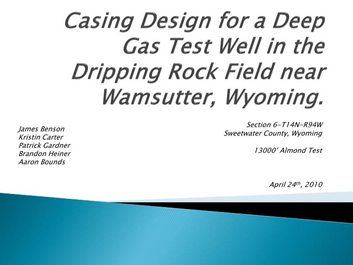
Casing Design for a Deep Gas Test Well in the Dripping Rock Field near Wamsutter , Wyoming. James Benson Kristin Carter Patrick Gardner Brandon Heiner Aaron Bounds. Section 6-T14N-R94W Sweetwater County, Wyoming 13000’ Almond Test April 24 th , 2010. Synopsis. Introduction

E N D
Casing Design for a Deep Gas Test Well in the Dripping Rock Field near Wamsutter, Wyoming. James Benson Kristin Carter Patrick Gardner Brandon Heiner Aaron Bounds Section 6-T14N-R94W Sweetwater County, Wyoming 13000’ Almond Test April 24th, 2010
Synopsis • Introduction • Health, Safety and Environmental • Geology / Hazards • Mud program • Casing Design criteria • Casing Program • Economics • Conclusion, Q&A
Introduction • Purposes of casing: • Protects and isolates wellbore and surrounding formations • Prevents contamination of water sources and, vice versa, keeps unnecessary water out of the produced fluids • Strengthens wellbore • Can hold back weak formations from sloughing into wellbore and also keeps overweighted drilling fluids from fracturing and entering weak formations
What is casing? • Casing pipe itself is basically a standardized large-diameter pipe • Casing grades are denoted with a letter for tensile yield and an abbreviated number for yield strength • “J-55” grade steel can withstand 55,000 psi before it starts to fail • In general, stronger casing (like P-110, for example) is more susceptible to hydrogen sulfide (H2S) embrittlement due to the metallurgy
Health, Safety and Environmental • Safety procedures put in place can be the weight of the mud, additional rams, a larger gas buster, and a flare. The heavier the mud weight the more pressure is placed on the recovered product. The weight must be balanced with the pressure of the formation and the product. Too heavy mud can cause fractures in the formation which can also be problematic. • The additional rams may be put in place to ensure that if there is a well control issue then the BOP can be closed. • If a well is high pressure there stands the potential for a large amount of gas, increasing the size of the buster may help when that gas is coming to surface. • The flare will be used in conjunction with the buster to destroy the gas and help relieve pressure.
Geology • Six named formations must be traversed before reaching the Almond
Green River • Mixed oil shales, coals and sandstones • Possibility of losing circulation to natural fractures • Supplies Wamsutter with municipal water • Shallow formation (roughly 1500’)
Wasatch • Mudstone with sandstone lenses and coal seam cap • Lost circulation common • Depth of roughly 3000’
Fort Union • Mixed sandstones, shales and coal seams • Weak formation • Washouts common • Many coal seams can lead to lost circulation • Depth: 5800’
Lance • Mixed shale, siltstone, sandstone and coal seams • lost circulation is an issue • Depth approximately 9200’
Fox Hill • Sandstone • Known to contain uranium in other parts of the country , unknown here • Depth of roughly 10,200 feet
Lewis • Shale with bentonite stringers • Possible wellbore stability problems • Known to be a transition zone to higher (abnormal) pressures • Depth: 10,500 ft
Almond • Target zone • Mixed sandstone, bentonitic shale, coal seams • Known to be overpressured • Coal seams can take mud • Depth approximately 12,600 feet
Mud Program • Standard 8.5 ppg mud until about 6000 ft • Escalate mud weight to 10 ppg at 10,000 ft • Lewis formation (10,450 ft) is expected to be transition to overpressured zones • Increase mud weight to control formation pressures • Final mud weight should be between 14-16 ppg
Casing Design Criteria: • Account for swab and surge pressures by adding a margin on both gradients • Work from the bottom to top, starting at TD and using the least number of different casing sizes possible while staying between the gradient margins
Collapse Design Factor • Industry standard of 1.12 • Using tensile load as a factor to derate collapse pressure rating from Halliburton “Red Book” (or similar source)
Intermediate String: Tensile Load • As the length of a casing string increases, the weight of lower pipe adds to tensile stress and derates the pressure capability (as above) • Industry standard is a TDF of 1.8 • TDF= Joint Strength / Tension Load
Preliminary Design #1 This shows why a single piece of casing will not suffice. -One string will not allow adequate pressure control during the entire length of the wellbore even ignoring surge and swab pressure margins
Casing Design: Production Casing Using the above chart: • Bottomhole pressure will be around 9500 psi • For 5 ½ in. casing, P-110 grade (20 lb/ft) withstands 11,080 psi • This casing becomes “overkill” at about 10,000 ft • Could change casing to a smaller size or lighter grade steel to save money
Intermediate String From the pore pressure chart, the next casing should be designed around a “bottom” pressure of around 6200 psi • Needs to accommodate a 6 ½ inch bit • 7 ⅝ inch C-95 casing at 33.7 lb/ft withstands 9,380 psi • Appears to be overdesigned for pressure • Also need to consider tensile load – may be the limiting factor
Eliminating the 3-string design • The 2-string designs average $500k in materials • 3-string design runs $800k just for materials, on top of extra rig time (tripping, cement setup and crew, casing crew and other labor)
Optimizing 2-string design • Modified casing sizes for economics • Supported by other wells in the area • Used data from nearby wells • Formation data • Gas data • Production data
Economics Savings: $98, 240
Final Design • Saves almost $100k on materials, will not have significant effect on production ability • Surface casing: 9 ⅝ in. J-55 36 lb/ft to 1520 feet • String #1: 7 in. HCP-110 to 10,500 feet • String #2: 4 ½ in. P-110 from 10,000 to 13,000 feet • Tubing: 2 ⅜ in. L-80 from 13,000 feet to surface
Wellbore Schematic -Generated from Schlumberger’s I-Handbook
References • waterplan.state.wy.us/plan/green/techmemos/muniuse.pdf • Halliburton Cementing Tables, April 1999 • Applied Drilling Engineering, Bourgoyne et al, SPE 1991 • Wyoming Oil and Gas Conservation Commission, wogcc.state.wy.us/ • Toolpushers Supply Company, www.truecos.com/Toolpushers/default.htm • Devon Energy, www.devonenergy.com