Download
1 / 18
180 likes | 185 Views
Americas Region Civil Design. Tom Lackowski. Civil Design Criteria. Requirements for the Civil Design was derived by two major methods Desktop Studies

E N D
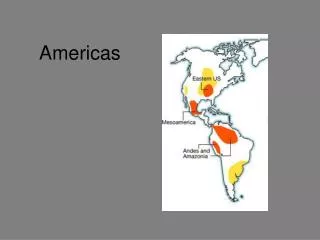
Americas Region Civil Design Tom Lackowski Global Design Effort
Civil Design Criteria • Requirements for the Civil Design was derived by two major methods • Desktop Studies • These studies used experts in various fields to establish scope of construction that is not derived directly from technical requirements. In general this firmed up elements of the RDR that were based on soft requirements or Engineering Judgments • Area System and Technical Requirements • This information both informal and formal came from Area System leaders, project technical experts, and project management. Many of these requirements have recently been formalized and posted in EDMS by Benno Global Design Effort
Desktop Studies (since RDR) • Configuration Study • Examined various options including cut and cover, soft ground tunneling and deep rock excavation. • Provided support that a single, deep tunnel, is optimized for an Americas Sample Site Global Design Effort
Life Safety Studies • Life Safety Studies • First study provided an analysis and recommendations based on an Americas fire safety code for underground construction • Second study performed computerized smoke migration analysis, confirming that the NFPA code provisions are appropriate. Global Design Effort
Surface Feature Study programmed shaft campus and buildings • Provided a rational basis for the campus buildings and site (quantities for estimate) Global Design Effort
Tunnel Cross Section Configuration Study • Examined tunnel inverts, tunnel linings, utility and technical equipment support anchorage Global Design Effort
Constructability Study • Proposed locations for TBM heading starts, TBM vs. drill and blast, schedule (advancement rate) , muck handling, water treatment and tunnel lining. Global Design Effort
Technical Requirements • Technical requirement inputs have been an ongoing pursuit since Snowmass 2004 • Main source of input have been the Area System leaders and Technical Area Leaders; tempered by Project Management • We know, or think we know, all of the major technical requirements that translate into space requirements which drive the costs. Global Design Effort
Key Plan • Main • Subpoint • Sub, sub point Global Design Effort
Major Cross Sections Global Design Effort
Dumps • Main • Subpoint • Sub, sub point Global Design Effort
Laser Equipment Current understanding is that the lasers will be placed in the service tunnel with no increase in the tunnel width. Exception is the e-source lasers, requiring an alcove Global Design Effort
Beamlines • All beamlines have been generated from geometry files (downloaded from EDMS), derived from lattices except for the Main Linac. • Ends of the Main Linac per, Tom Petersons layout, coincided with the end of the scripts. The length of the Main Linac fell within a fraction of a millimeter between the RTML warm section and the central region beam. • Except for the Damping Rings all of the geometry files were imputed from a common point; 0,0,0. Damping Rings were generated from Geometry File placed into position from Mark Palmers geometry description. Global Design Effort
Geometry files include line segments for Dumps/Aborts. • Last files inserted into drawing middle of last week. It took about two weeks time to get all of the files inserted into AutoCad. • Extents of Service Tunnel • Penetrations between Beamline and Service Tunnels • Dimensions of ~300kw dumps alcoves Global Design Effort
Main • Subpoint • Sub, sub point Global Design Effort
What needs to be done • We have the beamlines drawn, now we need to build the walls around the beamline so that quantity take offs can be accomplished. • The cad files are used to make area and volume rock excavation quantity take off • Other drawings such as sections sheets, plan details, arrow diagrams …. that are not used for estimate will follow at a lower priority. Global Design Effort