Download

1 / 64
650 likes | 674 Views
RT -UML. José M. Garrido Department of Computer Science Kennesaw State University. UML Diagrams. Structural Diagrams Class diagrams may also contain Objects Packages Actors Deployment Diagrams Component Diagrams Behavioral Diagrams Statecharts / Activity Diagrams Sequence Diagrams

E N D
RT -UML José M. Garrido Department of Computer Science Kennesaw State University
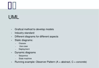
UML Diagrams • Structural Diagrams • Class diagrams may also contain • Objects • Packages • Actors • Deployment Diagrams • Component Diagrams • Behavioral Diagrams • Statecharts / Activity Diagrams • Sequence Diagrams • Collaboration Diagrams • Functional Diagrams • Use Case Diagram
Structural Diagrams • Diagrams serve many purposes • System model-capture & specification • View aspects of system design • Provide basis for communication and review • Diagrams bring two perspectives to the design process • Represent different aspects of design, eg • Functional • Structural • Behavioral • Quality of Service • Show aspects at different levels of abstraction • System • Subsystem • Component • “Primitive” class
UML Relations Primary Relations in UML • Associations • Normal association • Aggregation • Composition • Generalization • Dependency • <<bind>> for templates • <<friend>> for classes • <<includes>> and <<extends>> for use cases • Etc, etc etc
Collaboration • A collaboration defines a set of co-operating roles used collectively to illustrate a specific functionality. • A collaboration should only show the roles and attributes required to accomplish its defined task or function. • Isolating the primary roles is an exercise in simplifying the structure and clarifying the behavior, and also provides for re-use. A collaboration often implements a pattern.A collaboration element is shown as an ellipse.
A specification of a named contract offered by a class Notation: << interface>> a stererotype “lollipop” notation Interfaces
Associations • An association implies two model elements have a relationship - usually implemented as an instance variable in one class. • This connector may include named roles at each end, cardinality, direction and constraints. Association is the general relationship type between elements. • For more than two elements, a diamond representation toolbox element can be used as well. • When code is generated for class diagrams, named association ends become instance variables in the target class. So, for the example below, "playsFor" will become an instance variable in the "Player" class.
Aggregations • Aggregations are used to depict elements which are made up of smaller components. • Aggregation relationships are shown by a white diamond-shaped arrowhead pointing towards the target or parent class. • A stronger form of aggregation - a composite aggregation - is shown by a black diamond-shaped arrowhead and is used where components can be included in a maximum of one composition at a time. • If the parent of a composite aggregation is deleted, usually all of its parts are deleted with it; however a part can be individually removed from a composition without having to delete the entire composition. • Compositions are transitive, asymmetric relationships and can be recursive.
Aggregations • The following diagram illustrates the difference between weak and strong aggregations. • An address book is made up of a multiplicity of contacts and contact groups. A contact group is a virtual grouping of contacts; a contact may be included in more than one contact group. • If you delete an address book, all the contacts and contact groups will be deleted too; if you delete a contact group, no contacts will be deleted.
Stereotype • Adornment in a class • Used in two different ways: • As a “metatype”, e.g., <<subsystem>> • To tailor UML to meet a specific need or purpose
Dependency • In UML modeling, a dependency relationship is a relationship in which changes to one model element (the supplier) impact another model element (the client). • You can use dependency relationships in class diagrams, component diagrams, deployment diagrams, and use case diagrams. • You can also use a dependency relationship to represent precedence, where one model element must precede another. • Dependency relationships usually do not have names.
Dependency As the following figure illustrates, a dependency is displayed in the diagram as a dashed line with an open arrow that points from the client model element to the supplier model element.
Types of dependency relationships Because a dependency relationship can represent several different types of relationships, keywords or stereotypes are used to show the precise nature of the dependency.
Abstraction • «abstraction», «derive», «refine», or «trace» • Relates two model elements, or sets of model elements, that represent the same concept at different levels of abstraction, or from different viewpoints.
Binding • «bind» • Connects template arguments to template parameters to create model elements from templates.
Realization • «realize» • Indicates that the client model element is an implementation of the supplier model element, and the supplier model element is the specification.
Substitution • «substitute» • Indicates that the client model element takes the place of the supplier. • The client model element must conform to the contract or interface that the supplier model element establishes.
Usage • «use», «call», «create», «instantiate», or «send» • Indicates that one model element requires another model element for its full implementation or operation.
Using Dependency Relationships You can add dependency relationships to your model to accomplish the following goals: • Connect two packages to indicate that at least one model element in the consumer package is dependent on one model element in the supplier package. • The dependency relationship does not indicate that all model elements in the consumer package are dependent.
Dependency • Connect two classes to indicate that the connection between them is at a higher level of abstraction than an association relationship. The dependency relationship indicates that the consumer class performs one of the following functions: • Temporarily uses a supplier class that has global scope • Temporarily uses a supplier class as a parameter for one of its operations • Temporarily uses a supplier class as a local variable for one of its operations • Sends a message to a supplier class
Using Dependency Relationships • Indicate how to connect components to interfaces or other components • This shows that the components use one or more of the operations that the interface specifies or that they depend on the other component during compilation.
Example • In an e-commerce application, a Cart class depends on a Product class because the Cart class uses the Product class as a parameter for an add operation. • In a class diagram, a dependency relationship points from the Cart class to the Product class. The Cart class is, therefore, the client model element, and the Product class is the supplier model element. • This relationship indicates that a change to the Product class might require a change to the Cart class.
Packages • Packages are UML constructs that enable you to organize model elements into groups, making your UML diagrams simpler and easier to understand. • Packages are depicted as file folders and can be used on any of the UML diagrams, although they are most common on use-case diagrams and class diagrams because these models have a tendency to grow.
Component Diagram • The component diagram's main purpose is to show the structural relationships between the components of a system. • UML 2 officially changes the essential meaning of the component concept; in UML 2, components are considered autonomous, encapsulated units within a system or subsystem that provide one or more interfaces. • Although the UML 2 specification does not strictly state it, components are larger design units that represent things that will typically be implemented using replaceable" modules.
Component Diagram • Component diagrams illustrate the pieces of software, embedded controllers, etc., that will make up a system. • A component diagram has a higher level of abstraction than a Class Diagram - usually a component is implemented by one or more classes (or objects) at runtime. • They are building blocks so a component can eventually encompass a large portion of a system.
Component Diagrams • The previous diagram demonstrates some components and their inter-relationships. Assembly connectors "link" the provided interfaces supplied by "Product" and "Customer" to the required interfaces specified by "Order". • A dependency relationship maps a customer's associated account details to the required interface; "Payment", indicated by "Order". • Components are similar in practice to package diagrams, as they define boundaries and are used to group elements into logical structures. • The difference between package diagrams and component diagrams is that Component Diagrams offer a more semantically rich grouping mechanism. • With component diagrams all of the model elements are private, whereas package diagrams only display public items.
Representing Components • Components are represented as a rectangular classifier with the keyword «component» • Optionally the component may be displayed as a rectangle with a component icon in the right-hand upper corner.
Assembly Connector • The assembly connector bridges a component’s required interface (Component1) with the provided interface of another component (Component2) • This allows one component to provide the services that another component requires.
Components with Ports • Using Ports with component diagrams allows for a service or behavior to be specified to its environment as well as a service or behavior that a component requires. • Ports may specify inputs and outputs as they can operate bi-directionally. • The following diagram details a component with a port for online services along with two provided interfaces order entry and tracking as well as a required interface payment.
Deployment Diagrams • A deployment diagram models the run-time architecture of a system. • It shows the configuration of the hardware elements (nodes) and shows how software elements and artifacts are mapped onto those nodes. • A Node is either a hardware or software element. It is shown as a three-dimensional box shape, as shown below.
Node Instance • A node instance can be shown on a diagram. An instance can be distinguished from a node by the fact that its name is underlined and has a colon before its base node type. • An instance may or may not have a name before the colon. The following diagram shows a named instance of a computer.
Node Stereotypes • A number of standard stereotypes are provided for nodes, namely: «cdrom», «cd-rom», «computer», «disk array», «pc», «pc client», «pc server», «secure», «server», «storage», «unix server», «user pc» • These will display an appropriate icon in the top right corner of the node symbol
Artifact • An artifact is a product of the software development process. • That may include process models (e.g. use case models, design models etc), source files, executables, design documents, test reports, prototypes, user manuals, etc. • An artifact is denoted by a rectangle showing the artifact name, the «artifact» keyword and a document icon, as shown below.
Association • In the context of a deployment diagram, an association represents a communication path between nodes • The following diagram shows a deployment diagram for a network, depicting network protocols as stereotypes, and multiplicities at the association ends.
Node as Container • A node can contain other elements, such as components or artifacts. • The following diagram shows a deployment diagram for part of an embedded system, depicting an executable artifact as being contained by the motherboard node