Download
1 / 35
350 likes | 491 Views
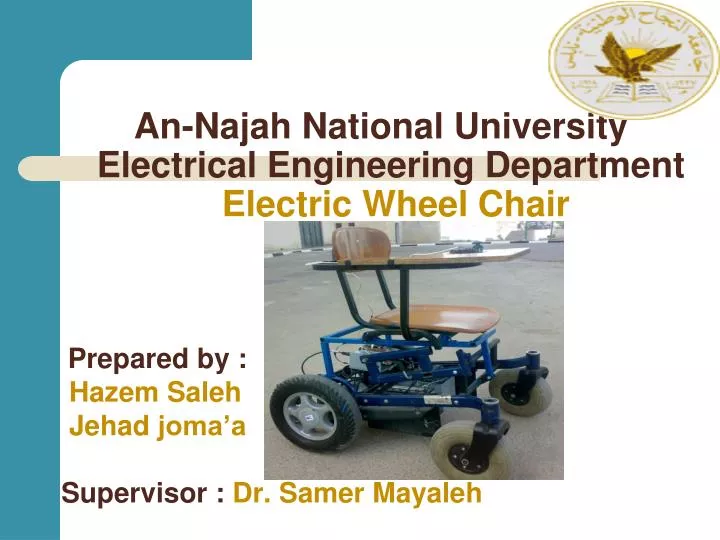
Prepared by : Hazem Saleh Jehad joma’a Supervisor : Dr. Samer Mayaleh. An- Najah National University Electrical Engineering Department Electric Wheel Chair. Contents. Introduction Project description Mechanical structure Dynamics calculations Motor selection

E N D
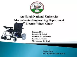
Prepared by : HazemSaleh Jehadjoma’a Supervisor :Dr. SamerMayaleh An-Najah National University Electrical Engineering Department Electric Wheel Chair
Contents • Introduction • Project description • Mechanical structure • Dynamics calculations • Motor selection • Transmission option • Motor control • Battery and charger • Future improvement
Introduction In this project we design and build an electrical wheel chair trying to help the special needs segment , and provide them electric chairs which are highly performance with low price compared with those in the local market .
Cont. • A people with special needs is( 3_4)% of the total population. • And the latest statistics for the disabled have proved that there is in Palestine, the highest proportion of disability in the Middle East but in the world by population • and the reason for the high number of disabled people is the occupation that uses bombs and missiles banned international and train soldiers on kill Palestinian , or you must shoot in his place cause paralysis until a permanent disability, we find that most of the injuries of the spine. • http://gudp.org/ar/?action=home
Project describtion:- • As shown in figure the project consists of: • Two motors. • Four wheels. • Simple structure chair. • Battery. • Microcontroller circuits. • Control unit (push buttons, joystick…)
Cont. • This wheel chair should be able : • Move forward. • Move backward. • Turn right. • Turn left.
Mechanical structure • Satisfies the international std. • Satisfies the main target • Simple to implement
Design specifications • Weight Capacity: 165 Lbs. , 75 kg • Maximum Speed: flat surface 6 MPH, 9.5 kmh, : incline sufrace 4 MPH, 6.4 kmh • Turning Radius: 33'' , 83.8 cm • Ground Clearance: 4.5" , 11.4 cm • Range of Travel: 25 miles per charge , 40.25 km • seat Width 18", 20" / 45.7 cm , 50.8 cm • Seat Length 16’’ / 40.6 • Seat Depths : 16" , 40.6 cm • Seat-to-Floor Height 19.5" / 49.5 • Backrest Height 17.5’’ / 44.5 • Overall Length: 41" , 104.1 cm • Overall Width: 23.5" to 27.5" , 59.7 cm to 69.9 cm • Overall height : 36.5 , 93 cm • Wheels: 12.5' , 31.8 cm" Drive /8' , 20.3 cm" Caster • Heaviest Piece: 100 Lbs ,45 kg
Dynamics calculations • On a flat area:- • V=6 mph V=9.6km/h • Tm = 18.3 N.m • Pe = 460 watt.
Dynamics calculations • On an incline area • V = 4 mph , V = 6.4km . • Tm = 33.6 N.m • Pe = 450 watt .
The Electrical Element Required: • Two DC permanent magnet motors. • Two Batteries 12V,26A • Voltage regulators. • Microcontroller. • the joystick • Optocouplers. • Power transistors. • Relays
Guiding factors for motor selection can be classified into four main categories as follows: • Electrical Considerations: starting and running characteristics, speed control and braking requirements. • Mechanical Considerations: type of enclosure, bearings, cooling, noise level and method of transmission. • Size and Ratings: requirement for continuous or variable load cycle and overload capacity. • Cost: capital and running costs.
Motor selection: Electric Motor GP 90 • AMT electrical motors are DC permanent magnet motors. • high degree of efficiency (up to 88%) and by low operating noise (45dB) • Motors can be run for a short time up to four times their rated torque. • rated power from 350 Watt to 550 Watt • 2 poles. • rated speed from 1500 to 4000 rpm(revolutions/minute) • Operating voltage 24V. • Outfitting with electromagnetic brakes possible.
Battery • (2×26Ah) 12v dry battery • Rechargeable • Safe operation • Long life cycle
Voltage regulators: • The 7805 is a VOLTAGE REGULATOR, It looks like a transistor but it is actually an integrated circuit with 3 legs. • turn it into a nice, smooth 5 volts DC. • You need to feed it at least 8 volts and no more than 30 volts to do this. • It can handle around .5 to .75 amps, but it • gets hot. Use a heat sink. • run off of 5 volts. • It can take a higher, crappy DC voltage and • Use it to power circuits than need to use or run off of 5 volts.
H-Bridge • An H-Bridge is a most commonly used for controlling devices like motors that requires current to flow in either direction, rather than just being turned on or off. • Simple to implement . • Easy to control • Wide range control • Forward • Reverse
H-Bridge USING RELAYS: • We use one relay to build the h-bridge : • Available • Low cost • could do same function • high current rating
Pulse width modulation (PWM) • The presence of PWM technique enables the motors to be speed contrled .
joystick: • The position of the joystick is calculated from the two potentiometers in the joystick. • The joystick can move in two dimensions which typically would represent any two dimensional quantity (X and Y ). • To read the potentiometers we use the analogRead() function(ADC).
Cont. • we use 3 push buttons : • the first push button used As stop • second push button used to increase the speed • the third push button used to decrease the speed
IRF P460: • Features :Fast switching timesLow RDS(on) Rugged polysilicon gate cell structureHigh Commutating dv/dt Rating • Mosfet ratingsVDss = 500 VID cont = 20ARDSon = 0.27 Ωdv\dt = 3.5 V\ns
Relay All relays operate using the same basic principle. Our example will use a commonly used 6 -pin relay. A de-spiking diode is connected in parallel with the relay coil. in reverse biased position when the relay is turned on no current will flow through the diode. When the relay control circuit turned OFF, current stops flowing through the coil, causing the magnetic field to collapse. inducing a counter voltage
PIC18 F4620 • 2- ADC inputs • 2-PWM outputs • 3-outputs(relay) • 3-interrupts (input)
Battery level LM 3914 Bar mode
Heat sink & cooling system: All semiconductor devices have some electrical resistance, just like resistors and coils , etc. This means that when power diodes, power transistors and power MOSFETs are switching or controlling reasonable currents, they dissipate power as heat energy, the heat must be removed to protect damaging the device .The most common way to do this is by using a heat sink
Future improvement • Multi input signals - wire less signal - touch bad (according to kind of disability)