Download

1 / 17
490 likes | 1.29k Views
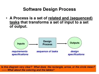
Software Design Process . A Process is a set of related and (sequenced) tasks that transforms a set of input to a set of output. Outputs. Inputs. Design Process. requirements specifications. sequence of tasks. design specifications.

E N D
Software Design Process • A Process is a set of related and (sequenced)tasks that transforms a set of input to a set of output. Outputs Inputs Design Process requirements specifications sequence of tasks design specifications Is this diagram very clear? What does the rectangle, arrow, or the circle mean? ------ What about the coloring and the lables?
Talking About Design (indirectly) • We will describe: • Notations usedto describe design activities • Design activities • Sequence of processing • Information (data) involved in the processing • Pointing out general design techniques: • Abstraction (& modeling) • Refinement (decomposition)
UML’s Activity Diagram • We use Activity Diagram to “model” the activities (sequence of tasks) in a system • main components (& its functionality) • relationship (interactions) among components • Activities (eventually decomposed down to functional actions, which are “atomic” in nature) • Activity Diagram also depicts the “Flow” of • Control • Data (information)
UML’s Activity Diagram • Software Design Process itself may be depicted or “modeled” with UML’s Activity Graph Diagram since a Design Process is composed of: • Activities or Tasks • Represented as action nodes (rounded rectangles) • Flow (of control &data) • Represented as arrows Token in begin Node Activity 1 Activity 2 Activity 3 This Activity Diagram depicts a “virtual machine” behavior of the process where there are tokens which run through the edges. 1) An action node begins Its execution when the tokens from all its incoming edges arrive. (implied synchronization) 2) When an action node begins execution it consumes all these tokens. 3) After a task is completed, the task node sends a token out on each of its outgoing edges. Activity 4 Token in End Node
UML’s Activity Diagram • Software Design Process may be depicted with UML’s Activity Graph Diagram since a Design Process is composed of: • Activities or Tasks • Represented as action nodes (rounded rectangles) • Flow (of controland data) • Represented as arrows Token in begin Node Read Req. Doc. analyze Requirements prioritize Requirements This Activity Diagram depicts a “virtual machine” behavior of the process where there are tokens which run through the edges. 1) An action node begins Its execution when the tokens from all its incoming edges arrive. (implied synchronization) 2) When an action node begins execution it consumes all these tokens. 3) After a task is completed, the task node sends a token out on each of its outgoing edges. Review Requirements Token in End Node
Decision and Merge Nodes • Besides the activity nodes and the edges, we need a mechanism to depict alternative flow based on some decision. • Decision node • Guard • Merge node Why do we need merge node here ? Req. Spec. Review 1) a decision node has a single entry edge, but multiple edges leaving it 2) a guard labels the “condition” that controls the flow through the edge (path) 3) a merge node has multiple entering edges but one exit edge Write Req. spec. Review Req. spec. [non-concur] [concur] A) If a token is available on any of the merge entering edges, it is passed to the leaving node. B) If a token is available on the decision node’s entering edge, a decision is made and a token is passed to the edge with the guard that depicts the decision Approve Req. Spec. Activity Symbol
Fork and Join in Control Flow(Explicit Synchronization) When a token is available on the incoming edge of a FORK Node (thick line), the token is duplicated and posted on all the outgoing edges of FORK Note : this is a bit like the Petri net Read Req. Doc. analyze Requirements prioritize Requirements Review Requirements When tokens are available on ALL the incoming edges of a JOIN Node (thick line), a token is placed on the outgoing edge Also: Read page 39 of your text on “flow final node”
Data may flow through an Activity Diagram. Data or object are shown as a rectangular figure, object node: Data tokens flow may be represented in the form of input pin and output pin: Data tokens and Data flow Write Req. spec. Written Spec. Spec. for review Req. Doc [reviewed] state of data Review Req. spec. reviewed spec. [non-concur] [concur] concurred Spec. Approve Req. Spec. Req. Doc [approved]
process name Data name and data type Activity Parameters Req. Spec. Review Process reqNotes: Docs apprReqSpec : Docs What about the input& output of the process? reqNotes - A process consumes inputs and produces outputs. - The inputs and outputs of a process may be represented as “parameters” to and from the process. - These parameters, in form of data or object node, are placed on the boundary of the activity symbol Write Req. spec. Written Spec. Spec. for review Review Req. spec. reviewed spec. [non-concur] [concur] concurred Spec. apprReqSpec Approve Req. Spec. approved Spec. Note that we have listed the parameters at the upper left corner of the Activity Symbol
When to Use Activity Diagram? May be used to depict the design (especially adescription of a set of actions) at either • High level (architectural and intermediate model) or • Low level (pseudo code level) depicting: • Activity • Control flow • Data and data flow (See page 45 of your text) Also, note that an action node in an activity diagram may itself be expanded into an activity diagram ----- giving us the capability of further refinement
Some Guideline to Activity Diagram Use Activity Diagram to “model” the dynamic (or flow) process. • Draw the flow control from left to right and from top to bottom. • Name activity nodes with verb phrases. • Name data nodes and datapins with noun phrases. • Use the guard and labels on every output edge of a condition node. • Use data flow, and not both control and data flow, whenever data flow alone can suffice. • Make sure that all flows entering a node can provide tokens concurrently, so that no deadlock can occur - - - or use merge nodes. Noted: the condition node and the merge node syntax, diamond, being the same, is NOT appealing ---- room for improvement
“High Level” Software Design Processusing Activity Diagram (Example) Software Design Process Needs & Wants: Doc Design Document: Doc Needs & Wants Product Design Analysis Product Design“Resolution” SRS Engineering Design Analysis Engineering Design Resolution Design Document
General Engineering Design Technique • 2 main steps: • Analysis of problem: Breaking Down, Understanding and clearly Defining the Problem • Design the solution : Finding the Solution(s) to the (Sub-)Problem(s) and Constructing the overall solution • Understand the problem and clearly defining it. (very important) • -------------------------------------------------- • Develop possible solution(s) • Evaluate the potential solutions • If there is a “best” selection, choose it; otherwise iterate through step 2 again. • Finalize and document the chosen solution
Software Engineering Design (in Activity Diagram) Software Engineering Design SRS : Doc Design Document: Doc Note: 1. Analysis is understanding the SRS SRS Engineering Design Analysis clear Problem Statements Generate Possible Solutions Note: 1. Generate more than 1 solution 2. Process is iterative Candidate Solutions Evaluate Candidate Solutions Select Solution [else-no solution] [selected solution] Selected Solution Design Document finalize/document the Solution
Two Levels of Software Engineering Design • Software Engineering Design (levels): • Architectural Level • Detailed Level • The previous Activity Diagram is “repeated” for each of the 2 levels, with different inputs and outputs. • SRS (analyzed) is the input for Architectural Design Level • Selected architectural design specification is the output for this level • Architectural design specification combined with SRS is the input to the Detail Design level • Detailed Design analysis analyzes the architectural design specification • Detailed design document is the output for Detail Design level Recall: - “Analysis” : breakdown, understand and further define - “Design” : propose solution alternatives; choose the solution; refine it; define it Redraw the previous activity diagram to depict the 2-level engineering design.
Software Design Management • Designing Software is an activity that resembles a project in itself. • Operations (regular recurring work - - - payroll, monthly finance, etc.) • ** Project (one time effort that starts and achieves specific goal) • Design Activities needs to be managed as a project with: • Planning • Organizing • Staffing • Tracking (monitoring) • Leadership-ing (adjusting and redirecting) Management of any project is very “iterative” between tracking and leading. But the process may also feedback to planning and re-adjust the plan
Managing any project depends a lot on how the work is decomposed – Design may be viewed as: Product Design Product Design Analysis: Understanding the overall customer problem Understanding the details of customers’ needs and wants Product Design Resolution: Reviewing, clarifying and prioritizing the overall problems and details Defining, documenting,& agreeing on the problem and details in SRS document Engineering Design Engineering Design Analysis: Study and analyze the SRS Engineering Architectural Resolution: Generating and documenting a high level architectural design document Engineering Detailed Design Resolution: Generating and documenting a detailed designed document Management Activities with this view of Design - WBS: Planning the following: Estimating of time needed Estimating resources needed Putting together a schedule Assessing risks Organizing the project Team structure Authority structure Tracking (monitoring) Schedule Design outputs-quality Leading (adjusting) Providing direction & support Managing Design Work This is the Work Breakdown Structure (WBS)