Download
1 / 19
190 likes | 322 Views
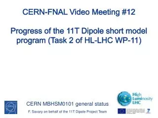
CERN-FNAL Video Meeting #13 Progress of the 11T Dipole short model program (Task 2 of HL-LHC WP-11). CERN MBHSM0101 and Plan for Future Models F. Savary on behalf of the 11T Dipole Project Team. Part I: Practice Model MBHSM0101. Main design features. Single aperture, 6-bloc design

E N D
CERN-FNAL Video Meeting #13Progress of the 11T Dipole short model program (Task 2 of HL-LHC WP-11) CERN MBHSM0101 and Plan for Future Models F. Savary on behalf of the 11T Dipole Project Team
Main design features • Single aperture, 6-bloc design • 56 turns • 22 on IL (4 blocs) • 34 on OL (2 blocs) • Aperture: 60 mm • Coil length: 1.8 m • Yoke OD: 510 mm • Shell thickness: 12 mm [AISI 304L] • One SC coil, ID105
Specific features • Copper coil #101 • End spacers CERN v0, longer coil • Sc coil #105 • Cable OST RRP 108/127 • ODS alloy wedges (Oxide Dispersion Strengthening ) • CERN V4 end spacers SLS (Selective Laser Sintering)with springy legs - hinge • Metallic saddles and splice blocks • External trace, glued on coil OD, carrying V-taps and quench heaters • Collars and yoke laminations produced by EDM (Electrical Discharge Machining) • Collars YUS130S Nippon Steel 3 mm thickness (LHC dipole) • Yoke laminations ArcelorMagnetil Low C steel 5.8 mm thickness (LHC dipole)
Assembly conditions - Winding D. Smekens J. Mazet • Winding tension: • Coil #101: 300 N; insulation defects: >1 • Coil #105: 250 N; insulation defects: 0 • Cable insulation • Coils #101 and #105: • Outer sleeve: AGY S-2 Glass 11 Tex, direct braiding • Inner dielectric: CogebiFirox 80 µm Mica – Fiber glass tape • Winding monitoring during coil #105 production Coils longer than expected: ~20 mm
Binder curing D. Smekens J. Mazet • Binder CTD 1202-X; qty: • Coil #101 IL: in excess; OL: in excess; • Coil #105 IL: 100 g; OL: 100 g; • Shimming: nominal (shimming such that in the press the mid-plane of the cured coil is like in the magnet; 0.12 mm above center axis) • This is different compared to FERMILAB where oversized shimming is used to compact the coil mid-plane beyond its nominal position in order to obtain a smaller coil size before entering into reaction • With a load of 0.8 MN, the mold is nearly closed (< 0.1mm) • Then, a load of 2 MN is used for IL, and 4.2 MN for the OL (complete pole) • The stress in the coils may not exceed 37 MPa at that stage
Reaction treatment D. Smekens N. Bourcey F. Lackner • Cavity of the reaction fixture is radially bigger than the curing mold by 0.1 mm; and of similar dimension at coil mid-plane • Thus, if the curing press can be closed before reaching 37 MPa, the coil cannot be subjected to higher stress when closing the fixture. However, the dry fiber glass, and the tight tolerances induce large friction; also, a possible dimensional problem with the sealing foils could have generated interference between the sealing foil and the baseplate, preventing correct closure of the fixture • The tightening torque to close the fixture was of the order of 300 Nm (FNAL applies 110 Nm to 160 Nm) • Not clear: no coil contraction after reaction, actually less that 1 mm, when 4.5 mm were expected
Reaction treatment – Coil 105 Adjustment of dwell time to compensate the delay between the temperature and tooling temperature The homogeneity of T during ramp up was not very good, ± 9°C. However, it is OK during dwell time N. Bourcey F. Lackner
Impregnation R. Gauthier D. Smekens • Resin: CTD 101K • Anhydride cured epoxy system with excellent performance at cryogenic temperature, and radiation resistance • The resin is preheated, and the coil is impregnated at 60°C • Curing @ 110°C for 5 hours • Post curing heating @ 125°C for 16 hours
Coils size • Both coils, 101 and 105, were oversized, only in the mid-plane • Best-fit on the outer diameter and the loading plates (interface with pole)
Collaring steps With 8MN the mechanical stops of the collaring tool were in contact
Shimming plan • Mid-plane is 650 µm beyond expectations. To compensate: • One layer of Kapton was removed on the mid-plane • Changed one layer of insulation to 0.05 µm thickness (in lieu of 0.125 µm)
Yoking / welding of the shells F. Lackner Max. charge: 500 t/m on central section to close the welding gap
Bullet gauges loading M. Guinchard P. Grosclaude 8 to 9 kN per bullet