Download
1 / 16
160 likes | 323 Views
HAWC High-resolution Airborne Wideband Camera. Facility Instrument for SOFIA Far-infrared camera covering the spectral range 40-300 µm Four filters at 53, 89, 155, and 216 µm 12 x 32 Pop-up Detectors (PUD) array cooled to 0.2˚K with adiabatic demagnetization refrigerator (ADR)

E N D
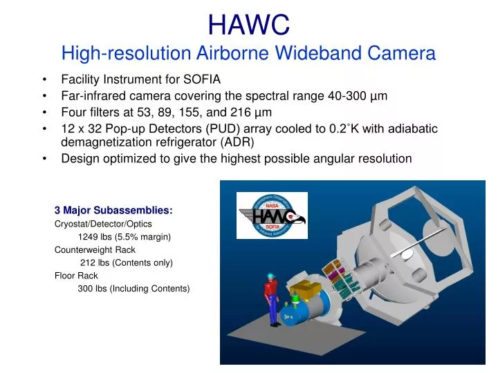
HAWCHigh-resolution Airborne Wideband Camera • Facility Instrument for SOFIA • Far-infrared camera covering the spectral range 40-300 µm • Four filters at 53, 89, 155, and 216 µm • 12 x 32 Pop-up Detectors (PUD) array cooled to 0.2˚K with adiabatic demagnetization refrigerator (ADR) • Design optimized to give the highest possible angular resolution • 3 Major Subassemblies: • Cryostat/Detector/Optics • 1249 lbs (5.5% margin) • Counterweight Rack • 212 lbs (Contents only) • Floor Rack • 300 lbs (Including Contents)
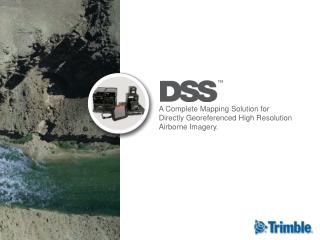
HAWC Detector Array • 12 x 32 implanted silicon bolometer array developed at NASA/Goddard (Moseley et al.)
HAWC Detector Array Detector array under cover JFET box
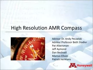
HAWC (OMS)Opto-Mechanical System Pupil/Filter Wheel
HAWC (OMS)Opto-Mechanical System Filter Wheel Pupil Wheel
HAWC Optical and Photometric Specifications22 June 2004 Items shaded pink need to be updated.
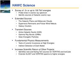
Detector Testing Results Preliminary Focused Beam Test Results (band 2 optics) • We see light!!! • circular PSF (within measurement errors) • detector to detector spacing at source: 1.27 mm • beam size: 1.9 pixels FWHM • optical response across rows does not show large variations Row 3 Row 2 time Overall Detector Testing Summary • 90% of pixels are working • changes in grounding and rf filtering have reduced noise to acceptable levels. (~10 – 50 nV/Hz1/2 with typical bias levels) • load curves predict NEPs of 4-5 10-17 W/Hz1/2 under nominal SOFIA conditions
Noise contributions Previous Est. New Estimates Units m pW nV/Hz 108 V/W 10-17 W/Hz nV/Hz V 10-17 W/Hz nV/Hz
Noise-Power Spectra (dark tests) Biased Input Grounded Input Signal (nV/ rtHz) Power spectra for two selected detector pixels (red plots are biased channels, blue plot is a grounded channel). 5–20 Hz amplitudes match prediction from model based on iv-curve data.