Download
1 / 19

E N D
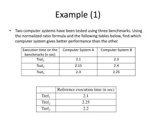
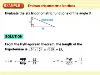
Example 1 A 9375 kVA, 13,800 kV, 60 Hz, two pole, Y-connected synchronous generator is delivering rated current at rated voltage and unity PF. Find the armature resistance and synchronous reactance given that the filed excitation voltage is 11935.44 V and leads the terminal voltage by an angle 47.96°.
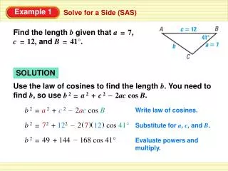
Example 2 A cylindrical rotor machine is delivering active power of 0.8 p.u. and reactive power of 0.6 p.u. at a terminal voltage of 1 p.u. If the power angle is 20°, compute the excitation voltage and the machine’s synchronous reactance.
Announcement • Quiz I : Next Tuesday (April 5, 2011) at 12:00 in H11 • Assignment I: will be posted today and due Next Tuesday (April 5, 2011) at 12:00 in H11
Transformation ratio Primary (supply) Secondary (Load)
Transformers at no load Ic E1 IF Qc E1 If Im f IF Ic Im The no load current If is needed to supply the no load losses and to magnetize the transformer core.
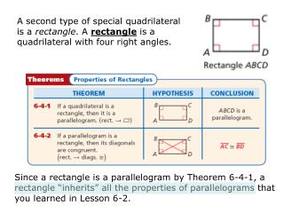
Transformer losses • The transformer losses are divided into electrical losses (copper losses) and Magnetic losses (Iron losses). • Copper losses in both the primary and secondary windings. • Magnetic losses, these losses are divided into eddy current losses and hysteresis losses.
Loaded Transformer Z2’ is the load impedance referred to the primary
Equivalent circuit V1: Primary voltage (supply) I1 : Primary current. V2: Secondary voltage (load) I2: : Secondary current
Approximate Circuit (a) (b) The no load current ranges from 1% to 3% of the full load current. Therefore, the circuit can be simplified to circuit (b).
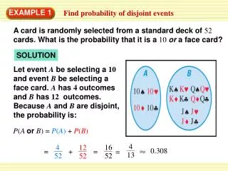
Performance Measures • The percent regulation • The transformer efficiency
Efficiency • The efficiency of the transformer is the ratio of output (secondary) power to the input (primary) power. Formally the efficiency is η: Where, P1 : The input power (Primary) = V1I1 cosf1 P2 : The output power (Secondary) = V2I2 cosf2 Where, PL is the power loss in the transformer = Pcopper + Piron
Example A 100-kVA, 400/2000 V, single-phase transformer has the following parameters R1 = 0.01 R2 = 0.25 ohms X1 = 0.03 ohms X2 = 0.75 ohms The transformer supplies a load of 90 kVA at 2000 V and 0.8 PF lagging. • Calculate the primary voltage and current using the simplest equivalent circuit. • Find also the V.R. and efficiency for the transformer