Download
1 / 17
170 likes | 296 Views
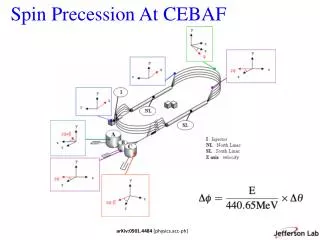
Driven Spin Coherent Precession at RHIC. Mei Bai, G. Bunce, R. Gill, T. Roser Brookhaven National Lab. Upton, NY 11973. Introduction. Spin motion near an isolated resonance

E N D
Driven Spin Coherent Precession at RHIC Mei Bai, G. Bunce, R. Gill, T. Roser Brookhaven National Lab. Upton, NY 11973
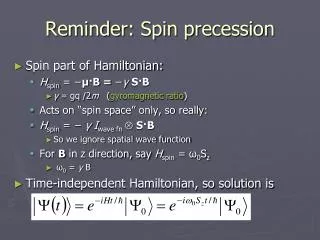
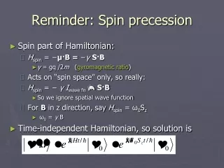
Introduction • Spin motion near an isolated resonance • spin vector gets away from vertical and precesses around vertical direction. The closer the spin tune to the resonance, the further the spin vector gets away from vertical. • Spin vector vertical component: remains constant. The vertical component averages to zero when on resonance • Spin vector horizontal component: precesses at an amplitude proportional to the strength of the resonance • The ratio of the average vertical component and horizontal precession amplitude can be used to determine the spin tune
Coherent Precession • Horizontal component Vertical component
Spin motion driven by a single ac dipole • Drives two resonances at Qs=Qsp and Qs=-Qsp. This introduces extra motion to the spin precession Rotating field Oscillating field • Spinor motion driven by a single ac dipole with horizontal magnetic field
Simulation of spin motion driven by a single ac dipole Spin vector not only gets bent away from vertical but also wobbles from turn to turn
Experimental Setup Fill pattern: two sets of 12 bunches with alternating spin signs • RHIC injection Gγ=45.5 • RHIC polarization setup: • two Siberian snakes opposite side of the ring axes about which spin rotates: perpendicular • spin tune Qs=1/2 • A single ac dipole at 4RF • Maximum strength: • 79 Gauss-m
Data Analysis (1) Data was taken with the RHIC CNI polarimeter Events for each detector each orbital revolution Horizontal asymmetry Y45 and vertical asymmetry X45 for each bunch in the frame which rotates at the ac dipole frequency
Data Analysis (2) • Average all the asymmetries for all bunches with the same spin sign, either up or down • Asymmetry due to the coherent spin precession • False asymmetry due to systematic
Data Analysis Average horizontal asymmetry for all the spin down (left) and spin up (right) bunches Down Up
Data Analysis Average vertical asymmetry for all the spin down (left) and spin up (right) bunches
Experimental Results (1) Observed a large false asymmetry.
Source of False Asymmetry 18 cm • The vertical coherent oscillation. This causes the oscillation of • solid angle Ω • False asymmetry ~ Ω2 • Scattering angle θ • False asymmetry due to coulomb scattering cross section θ dependence • Need actual geometry of the CNI polarimeter to estimate ultra-thin Carbon ribbon Silicon detector
Experimental Results (2) Multiple data sets show the measured spin precession in horizontal plane is insignificant.
Experimental Results (3) • The data suggests a rather large spin tune spread • In the presence of two full snakes, the source of spin tune spread • Difference in the divergence of the beam at the two snakes: ~ 0.002 for a 25 pi mm-mrad • Difference between the snake orbital angle due to dispersion: ~ 0.0001 • Simulation indicates spin tune spread modulate at low frequency like synchrotron oscillation can lead to large polarization loss Large polarization loss at the vicinity of the spin tune
Conclusion Ac dipole 1: Ac dipole 2: Spin rotator 1: Axis: vertical Angle 0: 90o Spin rotator 2: Axis: vertical Angle 0: -90o It is very difficult to excite coherent spin precessions with the single ac dipole setup at RHIC. Repeat the experiment with the new design of RHIC spin flipper
Acknowledgement Special thanks to E. Stephenson for helping the false asymmetry analysis Also would like to thank all the RHIC CNI polarimeter crew