Download
1 / 21
210 likes | 356 Views
Statechart -based representation of hybrid controllers for vehicle automation. IEE Proc. Intell . Transp. Syst. Vol. 153, No. 4, December 2006 Student : Wolin Lee. Introduction Statechart -based representation Verification issues of hybrid controllers Conclusion References. Introduction.

E N D
Statechart-based representation of hybridcontrollers for vehicle automation • IEE Proc. Intell. Transp. Syst. Vol. 153, No. 4, December 2006 • Student : Wolin Lee
Introduction • Statechart-based representation • Verification issues of hybrid controllers • Conclusion • References
Introduction Intelligent transportation systems (ITS), formerly called intelligent vehicle-highway systems, aim to improve the efficiency of current transportation systems by applying modern technology. One part of the ITS program, the automated highway system (AHS), promises to reduce traffic congestion and increase the safety, efficiency and capacity of highway systems without building additional highways. It does this by adding intelligence to both the vehicle and the roadside. The AHS control structure is centredon the concept of a platoon, which is a group of tightly spaced vehicles following a leading vehicle at highway speeds. The tight spacing between vehicles must be maintained without negatively impacting passenger safety (and comfort if possible).
The AHS control structure, shown in Fig. 1, is organisedin a hierarchy with five layers [1]. In the infrastructure system, the top network layer evaluates the traffic status of the entire highway system, calculates the desired densities and speeds to prevent congestion, and sends the appropriate commands to the link layer. Then, the link layer calculates an optimum platoon size and velocity for each section to maximise throughput. In the vehicle system, the coordination layer coordinates the operation of platoons with their neighbours. It receives the link-layer commands and translates them to specify manoeuvres such as the join, split and lane change [2]. Then, the regulation layer receives the manoeuvrerequests and computes the necessary commands to control the throttle, brake and steering actuators within the vehicles. The bottom physical layer is the actual automated vehicle with sensors that provide sampled information for the control algorithm.
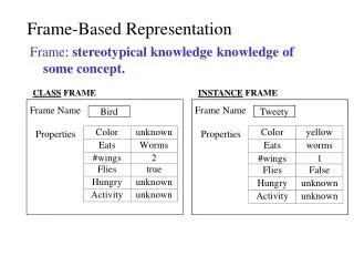
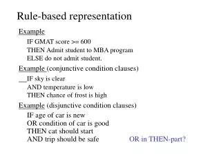
Statechart-based representation Statechart=(E, S,h,c,,A) • E is a finite set of basic events. • S is a finite set of state names. • h S ! is the hierarchy function. It defines for each state the set of children of that state. • c S ! { PRIM, AND, OR} is the class function. It gives for each state its type: primitive state, AND-state or OR-state. Primitive states have no children. ANDstatesconsist of two or more substatesgraphically separated by dashed lines. They introduce concurrency. OR-states contain a finite state machine with one or more substates. • S ! is the initial state function. It also gives the default substates of a state. • A is a finite set of arrows. The hierarchical control structure of AHS
A simple statechart The statechart of the UML is the primary means for capturing complex dynamic behaviours. It is inherently a language suitable for DES and handles the discrete behavioural representation for real systems. A traditional statechart represents a state machine and the sequences of states together with its responses and actions. Since it is basically developed for DES modelling, in order to capture the continuous dynamics, its extension for HDS modelling is proposed
The statechart modelling procedure for the HDS consists of the following steps: Step 1) Based on the specification, divide the system into several modules. Step 2) According to these modules, sketch a high-level statechart. Step 3) For each module, define the discrete states (S), events (E) and then connect the states with the arcs (A) in a logical order. Step 4) For each state with continuous dynamics, define the associated physical equations (f), transfer functions or other convenient means. Step 5) Based on D, set the initial conditions
This is a top–down approach for modelling a system in a hierarchical way, i.e. from high-level states to low-level ones, and from discrete behaviours to continuous dynamics. In addition, for large-scale systems,Step 1 provides a modular way to handle effectively the complexity. Also, the refinement can be applied tomodify the models. • The continuous variable state in the extended statechart
Hybrid controllers in automated vehicles The block diagram of the vehicle controller for automated vehicles is shown in Fig. 4. It is a typical hybrid control system, where a discrete-event coordination controller supervises and directs a discrete-time regulation controller so as to control a continuous-time system, in this case the vehicle dynamics. Thus, the coordination and regulation layer controllers within the automated vehicles form a hybrid control system. • The hybrid controller for automated vehicles in an AHS
Class diagram The class diagram in Fig. 6 represents the static structure and object relations of the vehicle system. The Vehicle class has a composition relation (represented as a black diamond), with the Vehicle Actuator and Vehicle Dynamics classes, and an aggregation relation (represented as a white diamond), with the Controller and Sensor classes. The composition relation indicates that the composite is explicitly responsible for the creation and destruction of the contained objects. The aggregation relation is also an ownership relation but is somewhat weaker than the composition relation. The three attributes of the Vehicle class imply that an automated vehicle lies in either a leader, a follower, or a free agent mode. The Controller class consists of the Coordination Controller class with three manoeuvre operations and the Regulation Controller class with six feedback control operations and, thus, leads to a hybrid controller. Other relations in the diagram are associations, indicating loosely coupled classes that send messages to each other in order to collaborate.
The dynamic behaviour of the hybrid controller. ( Fig. 7) Fig. 7 The macroscopic statechartof automated vehicle control
When the link layer sends commands to the coordination layer, the controller will analyse the platoon status and specify the necessary join, merge or lane change manoeuvre to perform. (Fig. 8) Fig. 8 The statechart for specifying manoeuvre
It generates the reference trajectories, including the desired jerk, acceleration, speed, spacing and yaw angle profiles, for the specified manoeuvre. (Fig. 9) Fig. 9 The statechart for generating reference trajectories
Before invoking the feedback control laws to perform a manoeuvre, the controller must make sure the requested action can be carried out safely. Thus, it performs certain safety checks, including checks of the vehicle status, given constraints and environment (Fig. 10) Fig. 10 The statechart for checking safety
The hybrid controller invokes the feedback control laws to perform the specified manoeuvre. The control laws use the reference trajectories and sensor signals to produce the throttle, brake and steering control inputs for the vehicle actuators. (Fig. 11) Fig. 11 The statechart for performing manoeuvre
These control signals are directly applied to the actuators and, thus, manipulate the vehicle dynamics so as to track the desired trajectories for the specified manoeuvre. After completing the manoeuvre, the controller lies in the Waiting state to wait for the next link-layer command.
Verification issues of hybrid controllers The aim of this paper is to present a statechart-based representation of the hybrid controllers for vehicle automation. Fig. 4 shows the hybrid controller comprising a discrete-event coordination controller and a discrete-time regulation controller. The verification method of the coordination layer could be found in , in which the logical correctness of the coordination controller was proved using a simple, finite state abstraction of the continuous dynamics. On the other hand, verification of the regulation controllers could be found in the past, in which mathematical transforms and root locus techniques were used to perform the analysis. However, it is possible for the regulation layer to produce certain undesirable behaviour, such as crashes, under severe disturbances. Thus, it is necessary to verify that the combined hybrid system does not result in vehicle crashes. To our best knowledge, at this time, no tools are available to analytically verify properties of such a complex hybrid system. In an AHS case especially, interaction between different vehicles, which are individually being controlled by the above mentioned hybrid control system, adds to the complexity of the verification. Owing to the lack of tools, simulation plays a very important role in the design of complex hybrid systems. There has been extensive work on the development of techniques for simulating general hierarchical hybrid systems . A specific simulation package, SmartPath, is developed for simulation of automated vehicles in an AHS. Even though simulation cannot replace formal proof techniques, it can still provide valuable information about the system performance. In this paper, the present work is to model the hybrid controllers based on a statechartrepresentation. Further verification and analysis of such complex hybrid systems would be investigated in the future.
Conclusion This paper has presented a statechart-based approach towards the hybrid controller representation for automated vehicles in an AHS. For modelling hybrid systems, the statechart of the standard UML is extended to capture continuous time behaviour with a clear and natural representation. Although the dynamics of the overall hybrid systems are very complicated, our work illustrates a more general approach of the hybrid controller representation for automated vehicles. Future work includes the study and comparison of the extended statechartfrom a theoretical point of view, the development of a powerful tool for automatic code generation and the fault tolerance ability with smart transition between the normal and automatic AHS driving. Also, analysis and verification of such a complicated hybrid system involving discrete event and continuous controllers is still an open question and could be further investigated.
References 1 Varaiya, P.: ‘Smart cars on smart roads: Problems of control’, IEEE Trans. Autom. Control, 1993, 38, (2), pp. 195–207 2 Hsu, A., Eskafi, F., Sachs, S., and Varaiya, P.: ‘Protocol design for an automated highway system’, Discrete Event Dyn. Syst.: Theory Appl., 1993, 2, (1), pp. 183–206 3 Huang, S., and Ren, W.: ‘Longitudinal control with time delay in platooning’, IEE Proc. Control Theory Appl., 1998, 145, (2), pp. 211–217 4 Stankovic, S.S., Stanojevic, M.J., and Siljak, D.D.: ‘Decentralized overlapping control of a platoon of vehicles’, IEEE Trans. Control Syst. Technol., 2000, 8, (5), pp. 816–832 5 Zhang, Y., Kosmatopoulos, E.B., Ioannou, P.A., and Chien, C.C.: ‘Autonomous intelligent cruise control using front and back information for tight vehicle following maneuvers’, IEEE Trans. Veh. Technol., 1999, 48, (1), pp. 319–328 6 Li, P., Alvarez, L., and Horowitz, R.: ‘AHS safe control laws for platoon leaders’, IEEE Trans. Control Syst. Technol., 1997, 5, (6), pp. 614–628 7 Shladover, S.E.: ‘Longitudinal control of automotive vehicles in close-formation platoons’, ASME J. Dyn. Syst., Meas., Control, 1991, 113, pp. 231–241 8 Koumboulis, F.N., and Skarpetis, M.G.: ‘Robust control of cars with front and rear wheel steering’, IEE Proc. Control Theory Appl., 2002, 149, (5), pp. 394–404 9 Redmill, K.A.: ‘A simple vision system for lane keeping’. Proc. IEEE Int. Conf. Intelligent Transportation Systems, Boston, MA, November 1997, pp. 212–217 10 Godbole, D.N., Lygeros, J., Singh, E., Deshpande, A., and Lindsey, A.E.: ‘Communication protocols for a fault-tolerant automated highway system’, IEEE Trans. Control Syst. Technol., 2000, 8, (5), pp. 787–800 11 Godbole, D.N., Eskafi, F., Singh, E., and Varaiya, P.: ‘Design of entry and exit maneuvers for IVHS’. Proc. American Control Conference, Seattle, WA, July 1995, pp. 3576–3580 12 Cassandras, C.G., and Lafortune, S.: ‘Introduction to discrete event systems’ (Kluwer Academic Publishers, Boston, MA, 1999) 13 Charbonnier, F., Alla, H., and David, R.: ‘The supervised control of discrete-event dynamic systems’, IEEE Trans. Control Syst. Technol., 1999, 7, (2), pp. 175–187 14 Lee, J.S., and Hsu, P.L.: ‘Design and implementation of the SNMP agents for remote monitoring and control via UML and Petri nets’, IEEE Trans. Control Syst. Technol., 2004, 12, (2), pp. 293–302 15 Lee, J.S., Zhou, M.C., and Hsu, P.L.: ‘An application of Petri nets to supervisory control for human-computer interactive systems’, IEEE Trans. Ind. Electron., 2005, 52, (5), pp. 1220–1226 16 Antsaklis, P., and Nerode, A.: ‘Hybrid control systems: An introductory discussion to the special issue’, IEEE Trans. Autom. Control, 1998, 43, (4), pp. 457–460 (special issue on hybrid control systems) 17 Lygeros, J., and Godbole, D.N.: ‘An interface between continuous and discrete event controllers for vehicle automation’, IEEE Trans. Veh. Technol., 1997, 46, (1), pp. 229–241 18 Booch, G., Rumbaugh, J., and Jacobson, I.: ‘The unified modelling language user guide’ (Addison-Wesley, Reading, MA, 1999) 19 Harel, D.: ‘Statecharts: A visual formalism for complex systems’, Sci. Comput. Program., 1987, 8, pp. 231–274 20 Eskafi, F., Khorramabadi, D., and Varaiya, P.: ‘SmartPath: An automated highway system simulator’. Tech. Report, Institute of Transportation Studies, University of California, Berkeley, 1994