Download
1 / 12
120 likes | 253 Views
Proteus Electrical Conformity Remediation. Several variants of the PROTEUS fluid flow switch are in use at the NSLS Two 120 VAC powered versions were found not to be compliant with the current EEI inspections The two models were not fused and did not ground the brass manifold.

E N D
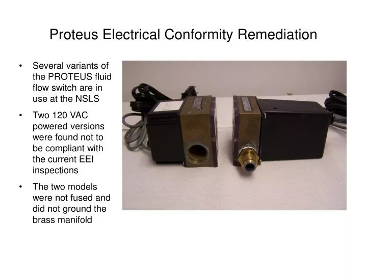
Proteus Electrical Conformity Remediation • Several variants of the PROTEUS fluid flow switch are in use at the NSLS • Two 120 VAC powered versions were found not to be compliant with the current EEI inspections • The two models were not fused and did not ground the brass manifold
Replacement of linecord • A NEMA 5-15P fused plug and cable assembly was found (distributed by Quail Electronics, inc. • The cord is UL listed and comes with a 10 amp fuse • It is 3 conductor cord with a full size ground conductor
Disassemble of old style PROTEUS • Loosen screw to on cable strain relief so that the power and signal cables can freely move • Remove the four machine screws holding the rear cover to the manifold block • Carefully record the color and orientation of the signal pickup wires. ( if the polarity is reversed during reassemble the pickup threshold may need to be adjusted.)
Gain access to the internal power connector • Pull the circuit card from the plastic cover. • The blue header can unplugged from the PC card to make it easier to work on the connector. • Note the connections : • G = Ground • N = Neutral • L = Line
Replace Linecord • Unfortunately the fused linecord did not come in a pigtail arrangement, so cut the IEC connector off the cable. • Strip about 3” of jacket from the cable. • Crimp on 18 AWG ferrules on the black and white wires using a ferrule crimping tool. Cut a peice of green, 18 AWG, PVC, 300 Volt hookup wire about 5” long. • Crimp one end of the wire with the power cord ground wire, the other end with and eyelet for a #6 screw.
Reattach the power connector • Place the line cord the feed-through / strain relief • Tighten ferrules in the connector • Verify that : • Green wire is connected to G • White wire is connected to N • Black wire is connected to L • Attach the ground eyelet to the brass manifold with a nickel plated brass #6 screw
Finish assembly • Slide the PC card in the slot molded in the plastic cover • Pull back excess signal and power cable • Tighten strain relief screw • Orient the manifold spade lugs and eyelet on the opposite of the PC card spade lugs • Install the four screws that hold the cover to the manifold.
Disassemble of new style PROTEUS • The new style Proteus is more compact that the old style • The length of the power and signal cord internal to the cover prevents the PC card from being removed. You must remove the strain relief's holding the power and signal. • Remove the four screws holding the cover • Remove the three screws holding the PC card
As before replace the line cord • Replace line cord as done in slides 5 and 6 • Remember to route the power cord through the feed through befor connecting the ferrules • Verify that : • Green wire is connected to G • White wire is connected to N • Black wire is connected to L • It is possible to reinstall the strain relief’s if the cables are extended about 1.5” internally. That’s enough to easily plug connector on to the pc board without having too much excess cable in the plastic housing.
Reinstall PC card and cover • Space is tight in the new cover. Flex the power and signal cables so that they do not pinch between the power transformer and cover. • Make sure that the PC card is free to sit flat on the plastic mounting standoffs. • Fasten the three PC board mounting screws • Align the eyelet at a 45 Deg. angle away from the spade terminals • There is only an small gap between the PC card and manifold. Make sure that ground wire does not cross itself or the eyelet. • Re attach the cover screws