Download
1 / 26
260 likes | 472 Views
Chapter 3 Continued. Logic Gates Logic Chips Combinational Logic Sequential Logic Flip Flops Registers Memory Timing State Machines. Lab Breadboard Strips. 4 Sets of connected pin holes run horizontally on the top and bottom of the strip

E N D
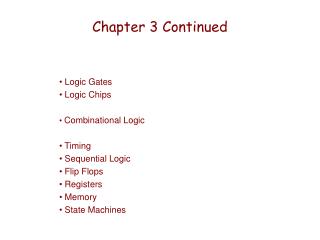
Chapter 3 Continued Logic Gates Logic Chips Combinational Logic Sequential Logic Flip Flops Registers Memory Timing State Machines
Lab Breadboard Strips 4 Sets of connected pin holes run horizontally on the top and bottom of the strip (good for running/connecting power and ground) Approximately 60 sets of connected pin holes run vertically in the middle of the strip (good for connecting power to pins and connections between pins) Note: Use Bell wire to make connections. You might want to color code wires by function.
Logical Completeness • Can implement ANY truth table with AND, OR, NOT. 1. AND combinations that yield a "1" in the truth table. 2. OR the resultsof the AND gates. • ALSO: • Can implement ANY truth table with ONLY NANDS. • Can implement ANY truth table with ONLY NORS.
Major Types of Flip Flops Non- Clocked • S R Clocked (Edge Triggered, LevelTriggered, Master/Slave) • D • J/K Note: D and J/K FlipFlops often have S & R inputs also
D Flip Flop (D Latch) D | Qn+1 0 | 0 1 | 1
JK Flip Flop J K | Qn+1 0 0 | Qn 0 1 | 0 1 0 | 1 1 1 | not Qn
JK as a Universal Flip Flop JK as an SR – use set and pre inputs JK as a Toggle – connect J and K JK as a D – connect NOT J to K
Register • A register stores a multi-bit (vector) value. • We use a collection of D-latches, all controlled by a common write enable pulse, call it WE. • When the write enable WE=1, the n-bit value D is written to register.
22 x 3 Memory word select word WE input bits address write enable address decoder output bits
Memory Design – 1K x 4 A[09:00] D[03:00] Addr Block Select
Memory Design – 1K x 8 D[07:04] D[03:00] A[09:00] A[09:00] D[07:04] D[03:00] Addr BlockSelect => Addr Block Select =>
Memory Design - 2k x 8 D[07:04] D[03:00] Block 01 Block 00
D[07:04] D[03:00] Memory Design - 4k x 8 Block 11 Block 10 Block 01 Block 00
More Memory Details Two basic kinds of RAM (Random Access Memory) • Static RAM (SRAM) • fast, maintains data as long as power applied • Dynamic RAM (DRAM) • slower but denser, bit storage decays – must be periodically refreshed. Refreshing interferes with regularity of execution of instruction stream. Also, non-volatile memories: ROM, PROM, flash, …
Alternative Logic “Family” Choices • Totempole: High or Low output level (Most Common) Line always at a 1 level or 0 level • Tristate: High, Low, or Open (Good for BUS application) Like Totempole, but has third state – open state • Open Collector, Open Drain, Wired-OR:(Older alternative to Tristate – still used, but more susceptible to noise) Line is nominally at a 1 level or 0 level – line is “pulled” to non-nominal level. Outputs of and gates can be connected directed together to create an “OR condition. • Differential:(Used for driving signals a distance. Good noise immunity) Uses a pair of lines – the “level” is the difference of signals on the two lines.
Combinational vs. Sequential Circuits • Combinational Circuit • always gives the same output for a given set of inputs • example: adder always generates sum and carry,regardless of previous inputs • Sequential Circuit • has memory - “stores” information, • output depends on stored information (state) plus input • so a given input might produce different outputs,depending on the stored information • example: ticket counter • advances when you push the button • output depends on previous state • useful for building “memory” elements and “state machines”