Download
1 / 73
740 likes | 892 Views
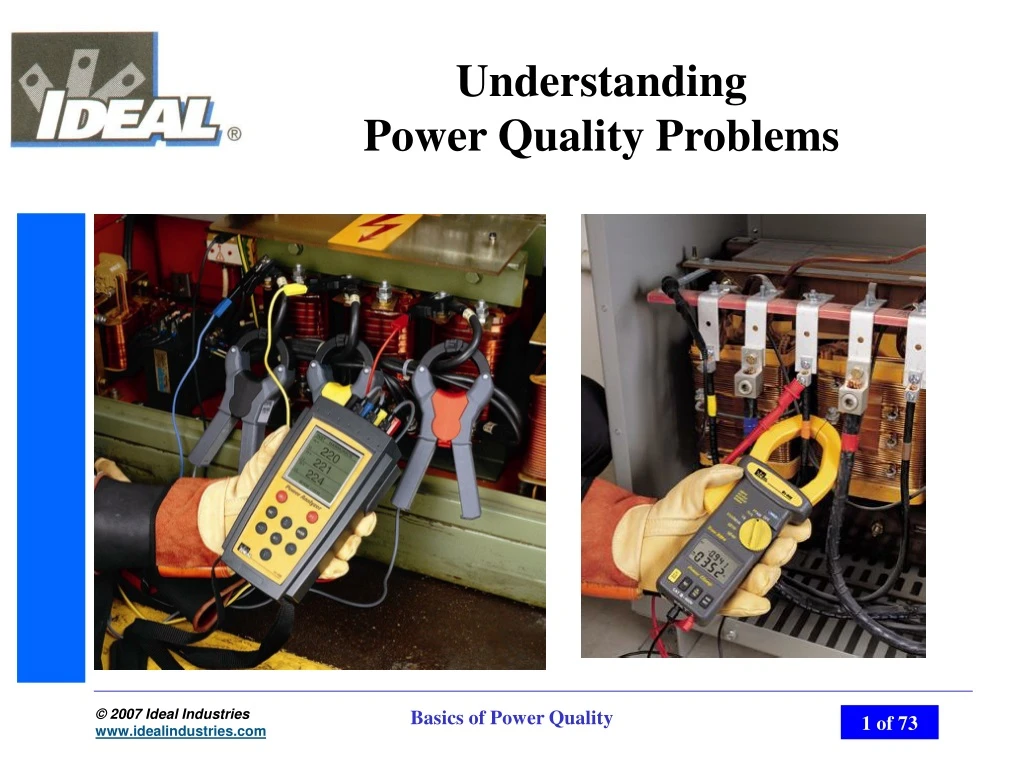
IDEAL Test & Measurement. Understanding Power Quality Problems. Objectives. This presentation has been adapted to NJATC Lesson 4-62. It’s intent is to give the student a basic understanding of Power Quality as describe in this lesson plan.

E N D
IDEAL Test & Measurement Understanding Power Quality Problems Basics of Power Quality
Objectives • This presentation has been adapted to NJATC Lesson 4-62. It’s intent is to give the student a basic understanding of Power Quality as describe in this lesson plan. • Describe the nature of several different types of power-related problems. • Identify the causes or source of many power related problems • List steps that can be used with different electrical equipment to minimize the equipment’s contribution to power-related problems. Basics of Power Quality
What is Power Quality Except for complete failure, most really don’t pay close attention to the power we are supplied. But if we were in the middle of an important document or key manufacturing process it would be more than a simple announce. A knowledge of power quality is necessary to identify and resolve electrical environmental problems Basics of Power Quality
What is Power Quality With the emergence of the “Electronics Age” there has be a change in the requirement of our electrical distribution systems. Unlike traditional load, like lighting or motors, Sensitive loads are more susceptible to power disturbances. Electronic equipment requires a much more stable power source. Basics of Power Quality
Importance of Power Quality • Consequences of poor Power Quality can result in: • Lost productivity • Lost/corrupt data • Damaged equipment • Poor power efficiency • U.S. companies waste an estimated $26 billion on electrical power-related issues each year* *Electrical Contractor Magazine, “Surveying Power Quality Options” March 2000 Basics of Power Quality
Power Quality • There is no absolute definition of power quality, but many define it as the degree to which both the utilization and the performance of electric power affects the performance of an electrical distribution system. • Organizations such as the IEEE -Institute of Electrical and Electronics Engineer and ANSI -American National Standards Institute are setting Stringent requirements for power Quality. • IEEE 519-81 Recommended limits on Harmonics • ANSI C84.1 Specification on normal voltage ratings and tolerances Basics of Power Quality
Key Contributors • Power Factor • Measure of how efficiently Power is used • Disturbances • Momentary disruptions to the Electrical system • Harmonics • Integers of the Fundamental Frequency which have an effect on the electrical systems and loads Basics of Power Quality
Power Quality • The NIST -National Institute of Standards and Technology publication NIST SP768 Shows that power disturbances can be defined in two categories, Steady State or Intermittent. • Steady state disturbances are Noise, Harmonics, long term Overvoltage or Undervoltage conditions. • Intermittent disturbances are Sages, Swells, Impulse, Transients, and interruption, Basics of Power Quality
ITI (CBEMA) Curve Basics of Power Quality
Power Factor • Incandescent lighting, heating elements, motors and capacitors • Affect on Electrical source are phase shifts due to capacitive and inductive reactance • Phase shift is measured as Power Factor or PF Most utilities have an additional charge if PF is less than .95 to .90 Basics of Power Quality
Power Factor • Apparent Power is the product of Volts times Amps • VA or KVA=V x A • Real Power is the time average of instantaneous product of Volts time Amps • W or kW = V x A x cosine theta • Time average of instantaneous evaluates phase shift between Volts and Amps • Power factor is Watts divide by Apparent Power • PF= W/VA Basics of Power Quality
Power Factor • VAR or Reactive Power is magnetic energy, which causes a phase shift between voltage and current Waveform • This overlapping of waveforms delivers less power to the load • VA2=VAR2 + W2 • VAR = Basics of Power Quality
VAR’s • VAR’s or the non-working energy may be thought of as water in a hose. • When water is first applied there is a slight delay before water gets to the end of the hose. • If we used a storage device, water at the end of the hose would flow immediately. Basics of Power Quality
Power Disturbances • Power disturbances generally fall into one of six categories. • Voltage Sags and Swells • Under-voltage or Over-voltage • Transients spikes, impulses and surges • Outages • Harmonics • Noise Basics of Power Quality
Power Disturbances • Voltage Sag • Momentary decrease in line Voltage • .5 to 30 Cycles (up to .5sec) • Caused by the start of heavy loads or fault occurrence on source. • Voltage Swells • Momentary increase in line Voltage • .5 to 30 Cycles (up to .5sec) • Occurs due to sudden load decrease or de-energizing of heavy equipment. Basics of Power Quality
Power Disturbances • Over-Voltage • Abnormally high voltage • >.5sec to a few seconds • Power voltage regulation • Under-Voltage • Abnormally low Voltage • >.5sec to a few seconds • Result for clearing of a fault or intentional utility regulation. Basics of Power Quality
Power Disturbances • Transients: • Short duration high amplitude pulses are surges that are superimposed on a normal voltage waveform. • Vary widely from twice the normal voltage to several thousand volts in time from < microsecond to a few hundreds of a second. • Result for loads cycling on and off in a building, utility, or lighting Basics of Power Quality
Power Disturbances • Outages • Outage is a complete loss of power lasting from a few milliseconds to several hours. • Caused by power system failure due to damage to supply lines or equipment failure Basics of Power Quality
Power Disturbances • NOISE: is an unwanted signal or distortion that is superimposed on a normal voltage waveform • Normal Mode noise • Common Mode noise • RFI: Radio Frequency interference • EMI: Electromagnetic interference Basics of Power Quality
Harmonics • Harmonics are multiples of the fundamental frequency of 60 Hz in an electrical system. • Most harmonics are generated from Non-linear loads, or solid-state device equipment • Examples are Computers, Copiers, Laser printers, UPS systems, industrial controls, welding machines, Adjustable Speed Drives {ASD} or Variable Speed Drives {VFD} Basics of Power Quality
Harmonics • Non-linear is used to describe the switch mode power supply {smps} found in most microprocessor based equipment and rectified supplies found in industrial loads. Basics of Power Quality
Harmonics • Non-Linear loads • Computers, printer, copiers, electronics lighting • Adjustable speed drives and other microprocessor controlled equipment • Effects on electrical systems or odd harmonics 3rd, 5th, 7th etc. Basics of Power Quality
Harmonics • Total Harmonic Distortion • Expressed as %THD • Percentage of distortion to the sine wave • Should not exceed 5% of line voltage or 20% of current • Harmonic FFT’s • Breakdown of the THD to the individual harmonics • Show the amount of harmonic as a percentage of the fundamental. Knowing each harmonic and its effect can help in determines the impact on the system Basics of Power Quality
Plan, Investigate & Test • Where to start • Plan your site survey • Investigate suspected areas • Test or monitor • Analyze results or date Please refer to Table 2 Electrical Distribution Systems Equipment and Grounding Measurement and Considerations Basics of Power Quality
Plan Make a block diagram of you facility. Basics of Power Quality
Investigate • Investigate suspected areas • Try to establish time of occurrence and duration history • Equipment usage cycles or new equipment instillation • Personnel • Interview others- Find out what they have observed Basics of Power Quality
Impulse • Most impulses are generated within a facility when inductive loads are switched on and off • Typical causes of impulses include switch contacts and sharp current transitions interacting with source impedance. Basics of Power Quality
Impulse • The origin of an impulses can be determined by reviewing the polarity of the leading edges of the simultaneous voltage and current impulses • If the voltage is “+” and current is “+”, or if the voltage is “-” and the current is “-” then the origin is source-related. • If the voltage is “+” and the current is “-” then the origin is load related. Basics of Power Quality
Voltage Sags • Voltage sags are sometimes caused by a problem on the utility power supply outside of the facility • If current on a circuit being monitored increases during a sag the origin is normal load related. • If current decreases or drops to zero during a sag the origin is normal source related. Basics of Power Quality
Voltage Sags • Other causes are, load interaction with wiring, (equipment at start-up) or voltage source impedance Basics of Power Quality
Voltage Distortion • Voltage Distortion can be caused by large harmonic currents from Nonlinear loads or Power sources with no sinusoidal Voltage Characteristic • Linear loads have small effects on voltage distortion. • Non-Linear loads have a larger effect on voltage distortion Excessive Current drawn as the Voltage waveform reaches Peak can cause Voltage distortion. Referred to as Flat Topping or Clipping. Basics of Power Quality
Ground to Neutral Events • Causes of neutral-to-ground voltage • Return current in neutral conductor • Excessive neutral conductor resistance • Ground current • Excessive ground resistance Ohm’s Law we can derive Voltage between Neutral And the ground. V=I * R, V= 50A * .1 ohm or V=5 Basics of Power Quality
Where to Look • Most power quality failures may be tracked down to one of three areas. • Supply- Utilities and its distribution. • Internal Distribution- Feeders and Branches, Grounding, wiring and termination • Internal Loads- load disturbances and Harmonics Basics of Power Quality
Supply- Utilities disturbance • Supply Disturbances and service area • Utility faults, • switching transients, regulation • Lighting, • Transients, outages • Accidents to Transmission lines • outages • Failure of backup sources • Outage, under of over voltages Basics of Power Quality
Internal Distribution • Inspect your Electrical distribution entrance service, ensure compliance with NEC. • Look for: • Check ground • Corroded connections • Defective conduit • Defective electrical devices • Adequate wiring Basics of Power Quality
Internal Distribution • Inspect all grounding, ensuring compliance with NEC. • Inspect receptacle, sub-panels, Feeder and etc, for proper grounding. • Inspect neutral to ground bonding per NEC compliance • Inspect Electrical panels. • Loose electrical connections, improper neutral to ground bonding at sub-panels. • Voltages phase to neutral , phase to ground, and phase to phase • Current in branch and feeders. Basics of Power Quality
Internal Loads • Identify major Loads • Computers • Copiers, Laser printers, and other Large office loads • HVAC Equipment • Industrial equipment, Like ASD’s (Adjustable Speed Drives) • Lighting • UPS systems Basics of Power Quality
Internal Loads • Transient • Inductive loads • Sags • Starting of large loads • Swells • Large load removed • Harmonics • Caused by solid-state electronics Basics of Power Quality
Effects of HarmonicsCommercial • Effects of Harmonics • Heating of Transformers • Heating of neutrals • Hot breakers and panels • High Voltage drop or Flat Topping • High Neutral to ground Voltage Basics of Power Quality
Effects of HarmonicsIndustrial • Effects of Harmonics • Heating of Transformers • Effects on Electromagnetic equipment • Power Factor Capacitors problems Basics of Power Quality
Transformers • Cause of Transformer heating • Harmonic currents cause an increase in copper losses and stray flux losses. • Harmonic voltage cause an increase in iron losses • Combined effect on transformer is heating Basics of Power Quality
Transformer • K-Factor rated transformers were designed to handle the additional heat generated by high harmonics. • Recommended Practice for Establishing Transformer Capabilities, • IEEE Standard C57.110-1986, • Never use a K-Factor that is higher than needed. It will reduce the transformers ability to withstand power glitches. • K rated transformers have lower impedance. You need some impedance to reduce effects of disturbances. Basics of Power Quality
De-rating Transformers • This method should only be used in de-rating phase to neutral loads. • Measure the True rms current for each phase • Measure the instantaneous peak for each phase • If the Ipeak and Irms values on each phase are not close, use the average value for each. • THDF= (1.414 x Irms)/ Ipeak. • (a value between 0 and 1.0) • KVA de-rated=KVAnameplate x THDF • (avg de-rating of a transformer is in the range of 20% to 40%) Basics of Power Quality
Hot Neutral Conductors • Neutral Conductors can have as much as 150% of triplen harmonics (3rd, 9th, 15th, etc) as any phase conductor. • Triplen harmonics don’t cancel, but add in the neutral conductor. • “Skin Effect”, higher frequencies travel not through the wire, but on the outer surface of the wire. • Small gauge wire have less surface so it is a higher resistance to the higher frequencies currents • This is one reason that conduit makes such a good ground for noise- the higher frequencies run on the surface of the conduit. Basics of Power Quality
Hot Neutral Conductors • Reducing the effects of hot neutrals • One is to up-size the neutral. In resent years this has been the most popular action. • Triplen harmonic filters could be used at key source panels. • This would reduce not only neutral currents but also help reduce phase to neutral load on transformers. • No shared neutrals. • In a 240/120 three phase distribution shared neutrals were common, but with so many SMPS being added to the electrical distribution performance wiring practice can reduce effect on power disturbances. Basics of Power Quality
Branch Circuits • Line to Neutral Voltage • Transients, Sags& Swells, Voltage drops, Flat toping • Neutral to Ground Voltage • Tripling harmonics, High ground impedance. Basics of Power Quality
Branch Circuit • Test receptacles in sequence along the branch circuit • Identify the receptacle where the voltage drop increases significantly • Check voltage drop on remaining receptacles • If voltage drop is acceptable in remaining receptacles, then problem is probably localized at receptacle connection • If voltage drop is unacceptable, then problem exists within the hot or neutral conductors Basics of Power Quality
Integrity of the Branch Circuit • If all branch receptacles have unacceptable voltage drops, then the problem is most likely in the circuit between the panel and the first receptacle, or at the panel • Undersized wire for length of run • Possible splices • Poor connections or corroded contacts at panel • Breaker, neutral bus, etc. • Most show up as hot spots in the panel Basics of Power Quality
Integrity of the Branch Circuit • Ground to neutral voltage measurement • Indicates feedback on the neutral conductor • Caused by load balance or harmonic • Three-phase 208/120V power systems • 2 volts or less is acceptable level of voltage • IEEE recommends 0.25 ohms or less for any phase conductor, Ground is not considered a conductor by NEC however it would be a good guideline to consider. Basics of Power Quality
Integrity of the Ground • Identify false grounds • False or “bootleg” grounds are defined as a short between neutral and ground • Accidental short or improper bonding of ground and neutral conductors • Shows up as normally wired condition with receptacle testers Basics of Power Quality Test & Measurement