Download
1 / 51
510 likes | 678 Views
Max-Planck-Institut für Plasmaphysik, EURATOM Assoc.-IPP. Overview of ASDEX Upgrade Results. Otto Gruber for the ASDEX Upgrade Team. Presented at the 21st IAEA Conference at Chengdu (China), 16 – 21 Oct 2006. Max-Planck-Institut für Plasmaphysik, EURATOM Assoc.-IPP. ASDEX Upgrade Team:

E N D
Max-Planck-Institut für Plasmaphysik, EURATOM Assoc.-IPP Overview of ASDEX Upgrade Results Otto Gruber for the ASDEX Upgrade Team Presented at the 21st IAEA Conference at Chengdu (China), 16 – 21 Oct 2006
Max-Planck-Institut für Plasmaphysik, EURATOM Assoc.-IPP ASDEX Upgrade Team: C. Angioni1, C.V. Atanasiu2, M. Balden1, G. Becker1, W. Becker1, K. Behler1, K. Behringer1, A. Bergmann1, T. Bertoncelli1, R. Bilato1, V. Bobkov1, T. Bolzonella3, A. Bottino1, M. Brambilla1, F. Braun1, A. Buhler1, A. Chankin1, G. Conway1, D.P. Coster1, T. Dannert1, S. Dietrich1, K. Dimova1, R. Drube1, R. Dux1, T. Eich1, K. Engelhardt1, H.-U. Fahrbach1, U. Fantz1, L. Fattorini4, R. Fischer1, A. Flaws1, M. Foley5, C. Forest6, P. Franzen1, J.C. Fuchs1, K. Gál7, G. Gantenbein8, M. García Muñoz1, L. Giannone1, S. Gori1, S. da Graça1, H. Greuner1, O. Gruber1, S. Günter1, G. Haas1, J. Harhausen1, B. Heinemann1, A. Herrmann1, J. Hobirk1, D. Holtum1, L. Horton1, M. Huart1, V. Igochine1, A. Jacchia9, F. Jenko1, A. Kallenbach1, S. Kálvin7, O. Kardaun1, M. Kaufmann1, M. Kick1, G. Koscis7, H. Kollotzek1, C. Konz1, K. Krieger1, H. Kroiss1, T. Kubach8, T. Kurki- Suonio10, B. Kurzan1, K. Lackner1, P.T. Lang1, P. Lauber1, M. Laux1, F. Leuterer1, J. Likonen11, A. Lohs1, • Lyssoivan12, C. Maggi1, H. Maier1, K. Mank1, A. Manini1, M.-E. Manso4, P. Mantica9, M. Maraschek1, P. Martin3, M. Mayer1, P. McCarthy5, H. Meister1, F. Meo13, P. Merkel1, R. Merkel1, V. Mertens1, F. Merz1, H. Meyer14, F. Monaco1, H.-W. Müller1, M. Münich1, H. Murmann1, Y.-S. Na1, G. Neu1, R. Neu1, J. Neuhauser1, J.-M. Noterdaeme1, M. Pacco-Düchs1, G. Pautasso1, A.G. Peeters1, G. Pereverzev1, S. Pinches1, E. Poli1, M. Püschel1, T. Pütterich1, R. Pugno1, E. Quigley5, I. Radivojevic1, G. Raupp1, M. Reich1, T. Ribeiro4, R. Riedl1, V. Rohde1, J. Roth1, M. Rott1, F. Ryter1, W. Sandmann1, J. Santos4, K. Sassenberg5, G. Schall1, H.-B. Schilling1, J. Schirmer1, A. Schmid1, W. Schneider1, G. Schramm1, W. Schustereder15, J. Schweinzer1, S. Schweizer1, B. Scott1, U. Seidel1, M. Serbu1, F. Serra4, Y. Shi16, A. Silva4, A.C.C. Sips1, E. Speth1, A. Stäbler1, K.-H. Steuer J. Stober1, B. Streibl1, D. Strintzi1, E. Strumberger1, W. Suttrop1, G. Tardini1, C. Tichmann1, W. Treutterer1, C. Tröster1, M. Tsalas17, L. Urso1, E. Vainonen-Ahlgren11, P. Varela4, L. Vermare1, D. Wagner1, M. Wischmeier1, E. Wolfrum1, E. Würsching1, Q. Yu1, D. Zasche1, T. Zehetbauer1, M. Zilker1, H. Zohm1.
Max-Planck-Institut für Plasmaphysik, EURATOM Assoc.-IPP Contributing Institutes 1 Max-Planck-Institut für Plasmaphysik, EURATOM Association-IPP, Garching, Germany 2 Institute of Atomic Physics, EURATOM Association-MEdC, Romania, 3 Consorzio RFX, EURATOM Association-ENEA, Padova, Italy, 4 CFN, EURATOM Association-IST Lisbon, Portugal, 5 Physics Dep., University College Cork, Association EURATOM-DCU, Ireland, 6 University of Wisconsin, Madison, USA. 7 KFKI, EURATOM Association-HAS, Budapest, Hungary, 8 Institut für Plasmaforschung, Stuttgart University, Germany, 9 IFP Milano, EURATOM Association-ENEA, Italy, 10 HUT, EURATOM Association-Tekes, Helsinki, Finland, 11 VTT, EURATOM Association-Tekes, Espoo, Finland, 12 LPP-ERM/KMS, EURATOM Association-Belgian State, Brussels, Belgium, 13 NL Risǿ, EURATOM Association-RISØ, Roskilde, Denmark, 14 UKAEA Culham, EURATOM Association-UKAEA, United Kingdom, 15 University of Innsbruck, EURATOM Association-ÖAW, Austria 16 IPP, CAS, Hefei, China, 17 NCSR Demokritos, EURATOM Association-HELLAS, Athens, Greece
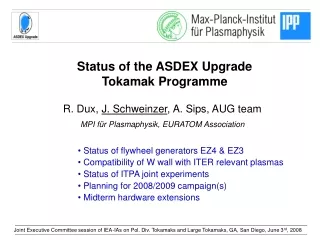
AUG programme to prepare / in parallel to ITER Main aim is to establish the physics base for ITER (and DEMO): - consolidation of the 'standard' H-mode scenario - exploration of ‚advanced' modes beyond the standard scenario Understanding of physics elements - transport - fast particles and NBCD - H-mode edge and ELM tailoring - disruption mitigation - MHD control with ECCD - tungsten wall and divertor operation Integration into improved scenario beyond reference - Improved H-mode (ITER Hybrid scenario) - ITER relevant digital CODAC system Direct influence on ITER component design: PFC material, heating/CD systems, ECRF system Strategy: in close collaboration within EU fusion programme, ITPA TGs
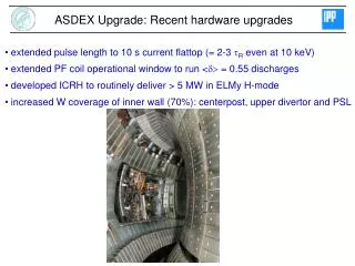
AUG enhancements 2004-2006: towards a tungsten first wall: 36 m2 or 85% of PFC area) 2005: - all LFS limiters (water cooled) - roof baffle with thin W coating (<4 mm PVD) 2006: lower divertor target plates (200 mm W VPS)
AUG enhancements: Towards a full W machine 2005 ● in 2005 “thin” W coating of - 4 guard limiters at LFS (water cooled) - 8 ICRH antenna side limiters - top of bottom PSL - roof baffle ● in 2006 - upper and lower ICRH limiters - W coated bottom target tiles (200 mm) full tungsten machine ITER start-up configuration ?
AUG enhancements 2004-2006: towards a tungsten first wall: 36 m2 or 85% of PFC area) 2005: - all LFS limiters (water cooled) - roof baffle with thin W coating (<4 mm) 2006: lower divertor target plates (200 mm W) 4 steerable ECRH mirrors installed first two-frequency gyrotron: leak after commissioning (≤1 MW / 10 s / 105 & 140 GHz) pellet injection systems -centrifuge (HFS launch capability, variable pellet size,< 1200 m/s) -blower gun (optimized for decoupling ELM pacing and refuelling) new CODAC commissioned - reduced cycle time <1.5ms - extended regime recognition & performance control - real-time diagnostics replaces CAMACs
Understanding of anomalous transport predictions - response of different transport channels on heat and momentum input - comparison with gyrokinetic simulations • TEM and ITG turbulence dominate in different parameter regimes Pure electron heating: threshold for TEM at R/LTe3 Angioni EX/8-5Rb power balance and heat pulse propagation show a transition through threshold
H98(y,2) Transport: Er transitions at plasma edge • negative Er well increases • with confinement improvement - coincides with H-mode barrier gradient - Doppler reflectometry Conway EX/2-1
f (kHz) time (s) Fast particle interactions with large scale instabilities • New: Fast Ion Loss Detector (FILD) with bandwidth of 1 MHz • frequency / phase correlations of fast ions with TAEs(ICRH, ICRH beatwave) • fast particle losses correlated with low frequency MHD activity: NTMs, double tearing modes, ELMs - slow MHD activity like NTM (+harmonics) induces fast particle losses - FILD signal is modulated with rotating mode in fixed phase relation - modulated NBI sources with different injection geometry origin of fast particles • time scale of losses >100 toroidal orbit transits due to stochasticity of overlapping drift islands caused by the NTM - NTM stabilization decrease of losses (2,1) Fast ion losses track the details of the mode Günter EX/6-1
UL(V) 4.2 s 0.1 s 3.5-4.0 s r Switch on / off-axis at 4.1 s Unexpected broadening of NBI driven currents - beyond a certain heating power, measured and predicted distributions of NBI driven currents deviate (MSE, TRANSP) - electric field changes cannot be explained by current diffusion Günter EX/6-1, McCarthy TH/P3-7
UL(V) 4.3 s 4.4 s4.5 s 4.2 s 0.1 s 3.5-4.0 s r Switch on / off-axis at 4.1 s Unexpected broadening of NBI driven currents - beyond a certain heating power, measured and predicted distributions of NBI driven currents deviate (MSE, TRANSP) - electric field changes cannot be explained by current diffusion Günter EX/6-1, McCarthy TH/P3-7
UL(V) 4.3 s 4.4 s4.5 s 4.2 s 3.5-4.0 s r Switch on / off-axis at 4.1 s Unexpected broadening of NBI driven currents - beyond a certain heating power, measured and predicted distributions of NBI driven currents deviate (MSE, TRANSP) - electric field changes cannot be explained by current diffusion energetic particle diffusion driven by small-scale turbulence (gyrokinetic code) • redistribution of injected ions • with Dfast0.5 m2/s Günter EX/6-1
ELMs and disruptions • most of the ELM and disruption energy is deposited in the divertor • a smaller fraction goes to the main chamber wall ITER: small ELM regimes / ELM pacemaking & disruption mitigation mandatory • ELMs: • - helical field aligned structures • with a 3-6 cm spatial width • and 3-6 km/s rotation velocity • move radially far into the SOL (LFS) • heat flux decay length 2-3 cm - particle flux decay length comparable • consistent with convective loss along field lines Neuhauser EX/P8-2
w/o gas puff Erad (kJ) w. gas puff vertical bolometer channels ELMs and disruptions • most of the ELM and disruption energy is deposited in the divertor • a smaller fraction goes to the main chamber wall ITER: small ELM regimes / ELM pacemaking & disruption mitigation mandatory • Disruptions: • mitigation by puffing of noble gases (Ne) regularly used at AUG - significant reduction of force loads on all structures • divertor heat load mainly reduced by broader radiation and heat deposition profiles in divertor • further optimization needed: higher gas pressure and amount Pautasso EX/P8-7
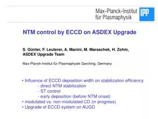
tor NTM stabilization: Influence of ECCD deposition width d narrow deposition W>2d: - IECCD counts for helical CD - full stabilisation with dc ECCD of (3,2) and (2,1) NTMs - no advantage of phased ECCD broad deposition W<2d: - mimics ITERWmarg~rpol - IECCD/d2 counts for dc ECCD - only partial dc stabilization - required current increases significantly ⇒ modulated ECCD required (at mode frequency / O-point injection)
X-point modulation 184 O-point modulation 17 tor NTM stabilization: Modulated ECCD with broad deposition Zohm EX/4-1Rb Yu TH/P3-13 narrow deposition W>2d: - IECCD counts for helical CD - full stabilisation with dc ECCD of (3,2) and (2,1) NTMs - no advantage of phased ECCD broad deposition W<2d: - mimics ITERWmarg~r* - IECCD/d2 counts for dc ECCD - only partial dc stabilization - required current increases significantly ⇒ modulated ECCD required (at mode frequency / O-point injection)
O-point modulation X-point modulation j~IECCD/d W<2d ITER W>2d NTM stabilization: Modulated ECCD with broad deposition Confinement improvement Zohm EX/4-1Rb
100 10 peaking ofcW 1 0.2 0 0.1 PECRH/Ptot High-Z wall and divertor in ITER / DEMO pro: - tritium co-deposition with carbon - erosion of low-Z material - neutron bombardment destructs graphite con: - central radiation losses sets limit cW< some 10-5 DEMO ITER Sputtering source mainly from LFS limiters • CX neutrals Te(edge) - fast ions from NBI: depends on injection geometry antenna limiters with ICRH: 60-90% of W influx - sheath rectified E-fields accelerate impurities - drastic enhancement of all sources during ELMs Dux EX/3-3Ra Impurity transport • H-mode barrier ELM frequency control by pellet injection • neoclassical inward pinch • anomalous outward impurity transport enhanced by central heating (ICRH, ECRH)
W wall: Long term evolution of W concentration • wide distribution depending on plasma conditions: increase with W coverage, saturation of mean value around 10-5 - reduced cW at relevant central heating power and higher densities (ITER!)
W wall: Indications for transitions to W device reduction of C plasma content (standard H-mode discharge) • Migration / transport model - slow evolution due to strong C recycling - C ‚leaking‘ out of divertor important 11019 atoms/s remaining strong net erosion zone Dux EX/3-3Ra Noble gas retention / release: Schmid EX/3-3Rb
Reversed shear ~zero shear plasma pressure 5 strong q Standard H- mode 4 Reversed shear 3 weak 0 0.5 1 2 r/a ~ zero shear Standard H-mode 1 0 0 0.5 1 r/a Improved H-mode:Characterization of „advanced scenarios Reversed shear, ITB discharges: hollow current profile highNH/q952>0.25only transient • control of pressure and current delicate • high bootstrap fraction > 60% ss • transport bifurcation Zero shear, ‘hybrid’ discharges: elevated q(0) above 1 desirable stationarywith NH/q952 up to 0.4 • high b-limitclose to no wall limit • substantial bootstrap fraction 50% • no bifurcation, smooth evolution
DEMO Improved H-mode: Performance and operational range similar correlation of density peaking to n* • N = 2-3.3and H98(y,2) =1-1.5 • N above 3 achievable at q95=3-5 • operating at ITER collisionality and at densities close to Greenwald • stationary on several current diffusion times Sips EX/1-1, Weisen EX/8-4
Improved H-mode: Confinement • heat transport given by TEM/ITG turb. - stiff temperature profile - plasma energy connected with pedestal pressure (pedestal energy) • confinement improvement weakly correl. with more peaked density profiles pedestal top pressure enhanced - increases stronger than Padd0.3 - predominantly Te,i rise due to broader barrier width - pbarrierconst. Suttrop EX/8-5, Maggi IT/P1-6,
Improved H-mode: Influence of q-profile Scenarioswith limiter /divertor ramp-up,early / late heating: effect on q profile H98(y,2)=1.2, N=2.3 q954 H98(y,2)=1.5, N=2.9 q954 Stober EX/P1-7
toroidal mode number n frequency (kHz) time (s) sawteeth Improved H-mode: Influence of q-profile different MHD behaviour: both clamp the current profile slightly peaked current profile flat central current profile influence on transport: - theory tells us R/LTi~s/q - both quantities up to 25% enhanced for flat q-profile - in agreement with threshold from GS2 (gmax=wExB) edge pressure increased in case with flatter q-profile Stober EX/P1-7
dc, W/(2d)=0.6 q95=2.9 N2.6 H98(y,2)1.2 Improved H-mode:(3,2) NTM suppression with ECCD Sips EX/1-1 Zohm EX/4-1Rb • at low q95<3.5 large (3,2) NTM can develop strong impact on confinement • after stabilization transition to fishbone activity enhanced performance
Substantial progress for the benefit of ITER was achieved. • AUG focuses on integrated ITER scenarios and performance beyond reference • Understanding of anomalous transport and turbulence (TEM,ITG) proceeds: ITER: peaked density profiles and benign high-Z accumulation to be expected • Fast ions: - losses caused by MHD and anomalous diffussion important • - off-axis NBCD above a certain turbulence level questionable • Modulated ECCD needed for NTM stabilization of ITER reference scenario • ELM (pacemaking) and disruption mitigation (gas injection) schemes evolve • high-Z walls compatible with tokamak operation modes - impurity sputtering source by ICRF accelerated impurities critical - accumulation control by ELMs and central heating (a-particles) afforded • Improved H-mode / Hybrid scenario guides ITER beyond reference scenario • - ITER parameter range achieved (q95, n*, ne/nGW) • at H98(y,2)=1.1-1.5 and N=2.5-3.5 • - Q and prolonged pulse length at full current (q95=3) • - Q=10 and 1 h pulses at reduced current (q954) • - heating power of 73 MW may not be sufficient to achieve N3 for IPB98(y,2)
Main aim is to establish the physics base for ITER (and DEMO): - consolidation of the 'standard' H-mode scenario - exploration of ‚advanced' modes beyond standard scenario Understanding of physics elements - transportAngioni EX/8-5Rb, Conway EX/2-1, Jenko EX/8-5Ra, Weisen EX/8-4 - fast particles and NBCD Günter EX/6-1, McCarthy TH/P3-7 - H-mode edge and ELM tailoring - disruption mitigation Pautasso EX/P8-7 - MHD control with ECCD Zohm EX/4-1Rb, Yu TH/P3-13, Merkel TH/P3-8 - tungsten wall and divertor Dux EX/3-3Ra, Schmid EX/3-3Rb Integration into improved scenario beyond reference - Improved H-mode (Hybrid scenario) Pereverzev FT/P5-23 Neuhauser EX/P8-2, Chankin TH/P6-15, Scott TH/1-1 Sips EX/1-1, Suttrop EX/8-5, Stober EX/P1-7, Maggi IT/P1-6, AUG contributions to this conference
Technical incident with EZ4 at 27.04.06 flywheel generator EZ4 damaged construction 1986, power 220 MVA, total weight ca. 160 t number of pulses est. 75.100, operated for est. 7.900 h • eperimental campaign terminated • extent of damage: overhauling of generator rotor, new generator stator • operation in 2007 with EZ2 & 3 with only limited restrictions: 60% of all pulses possible with reduced coil voltages • full W machine will start with limited wall loads and discharge parameters - in medium-term the full power/energy supply is needed for all relevant ITER work
ASDEX Upgrade, JETand ITER: a stepladder similarity to ITER in coil system and divertor configuration - similar in geometrical configuration (linear dimensions scale 1:2:4) - different in size and therefore in dimensionless parameter r* similarity in cross-section - size scaling and extrapolation to ITER
EZ3 > 11 kA EZ3 ≤ 11 kA 20 A.C. Sips, W. Suttrop 15 Limit: 11 kA EZ3 (kA) 10 5 0 0.4 0.6 0.8 1.0 1.2 Ip(MA) Operation with reduced generator capacity (EZ2, EZ3) AUG uses three flywheel generators as power/energy source EZ2 (1.45 GJ / 167 MVA): toroidal field EZ3 (500 MJ /144 MVA) + EZ4 (650MJ/220MVA): OH, pol.field, add. heating Present settings for PF coils: reduced power and energy with EZ3 alone allow only 15 % of the last 2000 # (Ip<800 kA, Padd<5 MW, t<5 s) Reduced max. coil voltages (except divertor coils) reduced reactive power consumption (speed) about 60% of the last 2000 # are still possible Ip=800 kA, 5-10 MW, t5 s Ip= 1 MA, 5-7.5 MW, t3-4 s at lower dens.& triang. W program (highest priority in 2007) nearly without restriction full ELM and disruption control program restrictedhigh- discharges at low * and * strongly reducedNTM stabilization schemes • the planned short-term investigations can be done with only minor restrictions • medium-term the full power/energy supply is needed for all relevant ITER work
Diagnostic extensions 2005/ 2006 Integrated evaluation of core and edge data: - state-of-art core diagnostic suite - multi-system, good resolution SOL & divertor diagnostics New or extended diagnostics: Doppler reflectometry edge Ti and impurity densities from Li beam ultrafast (ns) Thomson digitisation for filament detection fast ion loss detector (new FILD at fixed positions) fast pellet observation (KFKI, Budapest) combined Langmuir and magnetic probes Diagnostics under development collective TS at 105 GHz (Risø) distribution of fast ions; radiation level? collective TS at 140 GHz (Nizhny Novgorod / WTZ) magnetic field direction extension of reflectometry bands (Q band, IST Lisboa) SXR crystal spectrometer (Moscow, ITER) tangential edge CXRS system (NBI source 3 as radial CXRS, MSE) fast ELM resolving camera SXR (48 out of 148 lines of sight) Enhancement of equilibrium reconstruction (CLISTE, FPJ)
Understanding of anomalous transport predictions Flattening of density profile with increasing collisionality: AUG, JET, TCV: - transition from dominant TEM to ITG turbulence - decrease of Te/Ti supports (heat pulse studies) - gyrofluid model GLF23 agrees, nonlinear gyrokinetik GS2 results disagree • Strong link between ion heat and momentum transport - colinearity between Ti and vtor - strong correlation between cF and ci-ci,neo: ratio decreases across radius • No anomalous central impurity accumulation with central auxiliary heating - quasi-linear estimates with GS2 - impurity outward pinch driven by ITG turbulence under experimental conditions - a-heating in ITER will do the job • Robust negative well of Er at plasma edge (Doppler reflectometry) - negative well coincides with steep H-mode barrier pressure gradient - Er shear enhanced as well
H98(y,2) Transport: Er transitions at plasma edge • negative Er well increases • with confinement improvement - coincides with H-mode barrier gradient - Doppler reflectometry • Er shear enhanced as well - 2 channel Doppler at fixed Df ~ 2GHz • - negative shear at pedestal • increases with confinement • - shear width 5cm Conway EX/2-1
beam switch-off beam switch-off 4 ms Fast particle interactions with large scale instabilities - Fast Ion Loss Detector (FILD) with bandwidth of 1 MHz - frequency / phase correlations of fast ions with TAEs (from ICRH beatwaves) - FILD spectrogram shows fast particle losses correlated with low frequency MHD activity: NTMs, double tearing modes, ELMs • FILD signal caused by DTM • response time depends on origin • orbit drifts and slowing down determine delay Unexpected broadening of NBI driven currents: - energetic particle diffusion driven by small-scale turbulence (gyrokinetic code) - redistribution of injected ions with Dfast0.5 m2/s
Fast particle losses caused by MHD activity FILD spectrogram shows fast particle losses well correlated with TAE activity (NBI, ICRH, ICRH beat waves) - ICRH creates trapped fast particles • vperp/v ~0.9, energy up to several hundreds keV - TAEs modify orbits of fast particles Munoz, K. Sassenberg, PhD, Cork, Ireland
NTM stabilization: Influence of ECCD deposition width d ITER: - threshold reduces with rpol AUG:- frequently interrupted NTM (FIR) allows higher ´s - ECCD with helical current within the island to compensate the missing BS current: jECCD>jBS
Full stabilisation of (3,2) NTM with modulated ECCD (d>W) W/(2d)= 1.2 • ECCD modulated with phase from magn. signals with fmode < 30kHz • reduced overall deposited ECCD power • complete stabilisation at high N / <PECCD> ~ 4.0 MW-1
ramp-up in divertor configuration q954.8 Te,i(0)4 keV Improved H-mode: Scenario development early versus late heating: Stober EX/P1-7
NI ramp-up in divertor configuration q954.8 Te,i(0)5.2 keV Te,i(0)4.5 keV Improved H-mode: Scenario development early versus late heating: performance increase Nand H98(y,2) differences disappear at higher heating powers Stober EX/P1-7
Improved H-mode: Confinement • heat transport given by TEM/ITG turbulence - stiff temperature profile - plasma energy connected with pedestal pressure (pedestal energy) • confinement improvement weakly correlated with more peaked density profiles - flatter density profiles anyway due to central heating (impurity accumulation!) Suttrop EX/8-5
rpol rpol Scenario development for ‚Improved H-Mode‘ • early versus late heating Reich, Stober
Improved H-mode Ip=14.2MA. q95=3.2 Paux=0 Q 1200 Ip=11.8MA q95=3.8 Paux=52 MW Q=11.4 1000 bN,th = 2.5-3 Ip=9.7MA q95=4.6 Paux=55 MW Q=6.5 800 standard H-mode Ip=14.7 MA, q95=3.1 Paux=78 MW Q=8 Pfus (MW) 600 ITER 15 MA bN,th 2.0 400 200 open symbols Paux > 73 MW closed symbols Paux≤ 73 MW 0 10 11 12 13 14 15 Ip- ITER (MA) Improved H-mode: predictions for ITER Extrapolation to ITER using AUG kinetic profile shapes and IPB98(y,2) scaling q95, N as in AUG, <n>/nGW=0.85, Te=Ti Pfus Paux, Q Sips EX/1-1
23.5 MW/m² 16.2 MW/m² 10.8 MW/m² 6.5 MW/m² Tsurf (°C) density 95% bulk W 90% bulk W 4.2 MW/m² pulse length (s) Test of W VPS coatings for divertor strike-points 200µm W VPS coatings on graphite with adjusted thermal expansion: (Plansee, Sulzer Metco) • screening: 4 – 23 MW/m² • cyclic loading: 10.8 MW/m², 3.5 s, > 100 pulses coatings are qualified for use in the lower divertor H. Greuner heat load tests in ion-beam facility GLADIS
4 AUG DIII-D bN 3 ITER 2 JT-60U 1 JET ITPA open: <10tE closed: >10tE 0 0 5e-3 1e-2 1.5e-2 ri* Development of ‚Improved H-Mode‘ (Hybrid mode) • Combination of high power, flexible addititional heating, current and shaping capability, density operation up to Greenwald and long pulse length (> current diffusion time) allows unique exploration of advanced scenarios beyond ITER baseline • Improved H-Mode in ITER allows Q>30 and / or pulselength above 1 h • Improved H-Mode may allow even ‚steady state‘ in DEMO
ECRF system: summary and outlook • successful long pulse tests in factory test stand • long pulse tests at IPP hampered by load performance: few 10s pulses achieved up to 600kW at 105GHz and 800kW/140GHz • frequency drift during a gyrotron pulse within the limit for future double disc window application at intermediate frequencies (max. 150 MHz at 140 GHz) • failure of vacuum conditions in the magnet lead to freezing of gyrotron cooling circuits; cavity deformation prevented further operation of the gyrotron • measures for continuous, temperature controlled water circulation envisaged • gyrotron Odissey-1 to be returned to GYCOM for repair • gyrotron Odissey-2 was successfully tested at GYCOM planned installation as 2f gyrotron in coming weeks • after repair, Odissey-1 will be equipped with double disc window planned operation as multi-frequency gyrotron end of the year
ECRH launching mirrors in sector 5 AUG enhancements:fast steerable ECRF launchers launcher mirrors: W / Cu - coated graphite Fast poloidal steering tested during ASDEX shots with B=-2.18T, Ip=800kA: a poloidal angle variation of 10° in 100 msec has been achieved D. Wagner
Future AUG hardware extensions ● Internal coils - besides RWM control many other applications (f=1/10 kHz); 2007-9 - compatibility w. RWM control; - compatibility with heating systems - diagnostic access (YAG,...); - relevant diagnostic development ●ICRH antenna fitting to shell installation befor shell mounting ? • LHCD 2008-10 5 MW at 3.7 GHz; 200 kA off-axis CD hardware and manpower from Associations needed ●Stabilising shell 2009-10