Download

1 / 21
210 likes | 402 Views
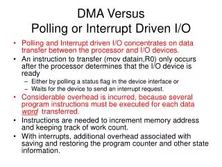
Microprocessor system architectures – IA32 interrupt handling. Jakub Yaghob. Overview. Sources of interrupts and exceptions External – HW interrupt , asynchronous , maskable SW interrupt – caused explicitly and synchronous using the instructions INTn , INT3 and INTO

E N D
Microprocessor system architectures – IA32 interrupt handling Jakub Yaghob
Overview • Sources of interrupts and exceptions • External – HW interrupt, asynchronous, maskable • SW interrupt – caused explicitly and synchronous using the instructions INTn, INT3andINTO • Exception – generated by CPU, when it detects some error • Vector system • IDT (Interrupt Descriptor Table) • Address and size provided inIDTR • Each handled event has assigned its vector number – 8-bit number (0-255) • Exceptions have fixed vector numbers in IA-32 • Assignment of vector numbers for HW interrupts leaved on external circuits • PIC, APIC
IDT – Interrupt Descriptor Table • IDT • As a matter of form similar to GDT • Descriptor table • Onlytask-gate, interrupt-gate, trap-gate • Loading IDTR similar to GDTR • The size of IDT is max. 256*8 • Can be smaller • In contrast to GDT, the IDT has valid vector number 0
Interrupt handling • Identify the vector number • External – supplied by interrupt controller using a bus protocol • NMI taken as an exception • Exception – fixed vector number by architecture • SW interrupt – vector number encoded explicitly or implicitly in the instructionsINTn, INT3andINTO • Indexing IDT using vector number • Using a gate in the IDT • The test EPL ≤ DPL for a gate computed only for instructionsINTn, INT3andINTO
Disabling and enabling interrupts • Only for external maskable HW interrupts • Changing IF • InstructionsCLI, STIfor CPL ≤ IOPL • POPF, silently ignored for CPL > IOPL • Task switch, return from interrupt – IRET • Interrupt handling using interrupt-gate • Masking interrupts and exceptions when switching stack • Atomic change ofSS:ESP • MOV/POPSSdisable external interrupts and debug exception until the end of the next instruction • All other exceptions use the oldSS:ESP
Gates II • Gates behavior • Nearly the same like thecall-gate • No parameter copying • EFLAGS automatically stored on the stack • ChangingEFLAGS content • Clearing flagsTF, VM, RF, NT • Interrupt-gateclearsIF • Some exceptions store error code on the top of the stack • It is the property of an exception, not a gate
Exceptions • Reserved range of vector numbers 0-31 • Classification • TRAP • State report • Reported immediately after the execution of the instruction • FAULT – „correctable“ errors • Reported „before“ the instruction • Instruction restart • ABORT – „unrecoverable“ errors • It is not usually possible to discover the exact instruction location • HW errors • Inconsistent system tables
Error code • EXT – external event • IDT – selector from IDT • TI – LDT/GDT (IDT=0)
Double fault – #DF • The second exception calling an exception handler for a prior exception • Interrupts divided into 3 classes • Benign – 1-7, 9, 16-19, INTn, INTR • Contributory – 0, 10-13 • Page fault – 14
Page fault – #PF • CR2 contains linear address which generated the exception • Conditions • The P flag in any page table level is cleared • Insufficient access rights • Access a page with CPL=3 and U/S=0 • Write to page with CPL=3 andR/W=0 • Write to page with CPL=0-2andR/W=0 and CR0[WP] =0 (from Pentium above) • Execution from page with NX=1 • Any reserved bit set to 1
Exceptions and interrupt handling in the long mode • Like in 32-bit mode with following exceptions • All interrupt handlers in IDT are in 64-bit code • Stack is 64-bit wide • SS:RSP always pushed • New SS is NULL when CPL changes • IRET behaves differently (always pops SS:RSP) • New interrupt stack mechanism • The alignment of stack is different (16-bytes-XMM registers)
Interrupt stack table • Individually enabled in descriptors • Part of the 64-bit TSS • 7 new stacks • IST=0 means old stack mechanism • Calling interrupt handler • RSP loaded from TSS[IST] • SS forced to NULL with RPL set to the new CPL • Old SS, RSP, RFLAGS, CS, RIP pushed on the new stack