Download
1 / 1

E N D
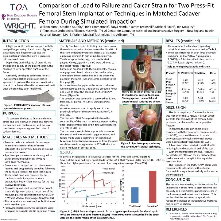
TOA William Kurtz1, Stephen Murphy2, Irina Timmerman3, Satya Nambu3, James Brownhill3, Michael Roark3, Jon Moseley31) Tennessee Orthopedic Alliance, Nashville, TN 2) Center for Computer Assisted and Reconstructive Surgery – New England Baptist Hospital, Boston, MA 3) Wright Medical Technology, Inc, Arlington, TN INTRODUCTION MATERIALS AND METHODS (continued) RESULTS (continued) A tight press-fit condition, coupled with the wedge-like geometry of a hip stem (Figure 1), puts substantial hoop stresses into the proximal femur when the stem is impacted into prepared bone. Depending on the degree of press-fit and the size and quality of the patient’s bone, this can lead to intra-operative fracture of the femur. A recently developed technique for less invasive implantation utilizes a modified approach to prepare the femoral canal in-situ in which the femoral head is not removed until after the stem has been implanted. • Twenty four hours prior to testing, specimens were thawed and cut off six inches below the distal tip of the stem and potted vertically inside a 3” diameter aluminum cylinder 3” high using dental acrylic. • Two hours prior to testing , two rosette strain gauges (Omega, gage L = 1 mm) were adhered to the calcar region. (Figure 2) • For femurs prepared with the traditional technique one gage was placed below on the medial calcar, 5mm below the resection line and the other was placed at the same level and 10mm anterior to the first gage.(1) • Distances from the gages to the lesser trochanter were measured on the traditionally prepared femur and used to place the gages on the SUPERCAP® femur. (Figure 3) • The construct was secured in a servohydraulic load frame (Mini-Bionix , MTS Inc.) using machine clamps. • A custom ram was used to apply load to the proximal surface of the hip stem at a rate of 25 mm/sec. • The ram was offset 5mm proximally from the superior flat of the stem to simulate impact loading. • Load, displacement, and strain data were captured at a rate of 200 Hz. • The maximum load to failure, principle strains for the medial and antero-medial gage locations, and failure mode were determined for each femur. • Maximum bone stress was calculated from the peak von-Mises strain using a value of 17.5 GPa for the elastic modulus of cortical bone. • The maximum load and corresponding principle stresses are summarized in Table 1. • The mean difference in peak force between traditional and SUPERCAP® groups was 1,660N (p = 0.01, two sided t-test, and p = 0.027, Wilcoxon signed rank test). Table 1: Average Peak Loads and Strain Comparison of Load to Failure and Calcar Strain for Two Press-Fit Femoral Stem Implantation Techniques in Matched Cadaver Femora During Simulated Impaction • Figure 2: Specimen prepared using the traditional surgical technique. Strain gages on the medial and antero-medial surfaces are shown. PURPOSE To compare the load to failure and calcar stress and strain between traditional femoral preparation and implantation and the less invasive technique using matched pairs of cadaver femora. DISCUSSION The force required to fracture the femur was higher for the SUPERCAP® group, which suggests that removal of the femoral head increases the chance of an intraoperativefracture. In general, the peak principle strain correlated with the peak force measurements (r = 0.573), but the differences in strain between experimental and control groups were not statistically significant (p>0.05). All constructs fractured with vertical splits initiating from the proximal end of the stem. With the traditional technique, fractures occurred more often on the medial or antero-medial area, with the split initiating at the resection line. The fractures in the SUPERCAP® group were more variable in location, with only one fracture initiating antero-medially and none on the medial side. MATERIALS AND METHODS • Ten matched-pair cadaveric femurs were imaged to screen for signs of severe osteoarthritis, deformity, tumors or existing proximal hardware. • Specimen pairs were randomly assigned to either the traditional or less-invasive SUPERCAP® technique. • Femurs were clamped into a custom frame, reamed and progressively broached following the surgical protocols for both techniques. • The femoral head was resected for the traditional technique prior to femur preparation, but was left in place for the less-invasive technique. • Fluoroscopy was used to verify final broach size and alignment prior to impaction of the modular, plasma-sprayed stem (PROFEMUR® Z, Wright Medical Technology, Arlington, TN). • The same size stem was used for both sides of each matched pair. • Following implantation, the specimens were wrapped, enclosed in plastic bags, and frozen. Figure 3: Specimen prepared using the SUPERCAP® surgical technique. RESULTS • In general the peak load to failure was greater for the larger size stems. (Figure 4) • Seven of the pairs had higher peak loads for the SUPERCAP® femur (delta range: 116 – 3961N), three had higher peak loads for the control technique (delta range: 45 – 470N) CONCLUSIONS The use of a less invasive, in-situ technique for implantation of the femoral stem resulted in a clinically and statistically significant increase in the force required to fracture the femur. This implies that the in-situ technique should reduce the chances of intraoperative fractures due to stem impaction. REFERENCES Elias JJ et al, “Medial cortex strain distribution during noncemented total hip arthroplasty” ClinOrthopRel Res 2000 (370):250-8. • Figure 4: (Left) A force vs displacement plot of a typical specimen pair. Sudden drops in force are indicative of bone fracture. (Right) The maximum stress recorded by the strain gages in the calcar region of the proximal femur. • Figure 1: PROFEMUR® Z modular, plasma-sprayed stem component http://www.wmt.com