Download
1 / 31
310 likes | 498 Views
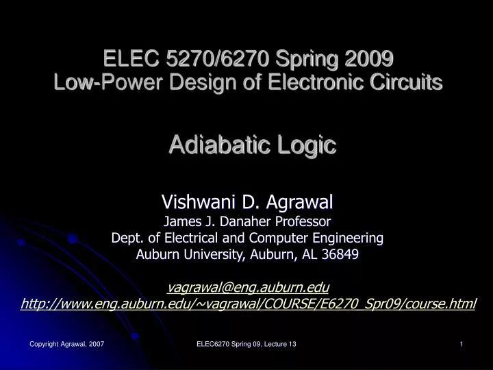
ELEC 5270/6270 Spring 2009 Low-Power Design of Electronic Circuits Adiabatic Logic. Vishwani D. Agrawal James J. Danaher Professor Dept. of Electrical and Computer Engineering Auburn University, Auburn, AL 36849 vagrawal@eng.auburn.edu

E N D
ELEC 5270/6270 Spring 2009Low-Power Design of Electronic CircuitsAdiabatic Logic Vishwani D. Agrawal James J. Danaher Professor Dept. of Electrical and Computer Engineering Auburn University, Auburn, AL 36849 vagrawal@eng.auburn.edu http://www.eng.auburn.edu/~vagrawal/COURSE/E6270_Spr09/course.html ELEC6270 Spring 09, Lecture 13
Examples of Power Saving and Energy Recovery • Power saving by power transmission at high voltage: • 1000W transmitted at 100V, current I = 10A • If resistance of transmission circuit is 1Ω, then power loss = I2R = 100W • Transmit at 1000V, current I = 1A, transmission loss = 1W • Energy recovery from automobile braking: • Normal brake converts mechanical energy into heat • Instead, the energy can be stored in a flywheel, or • Converted to electricity to charge a battery ELEC6270 Spring 09, Lecture 13
Reexamine CMOS Gate V2/ Rp V Most energy dissipated here i2Rp i = Ve–t/RpC/Rp v(t) Power V×i = V2e–2t/RpC/ Rp v(t) V C v(t) 3RpC 0 Time, t Energy dissipation per transition = Area/2 = C V 2/ 2 ELEC6270 Spring 09, Lecture 13
Charging with Constant Current V(t) i2Rp i = K Kt/C V v(t) = Kt/C C2V2Rp/T2 Output voltage, v(t) Power C 0 0 T=CV/K Time, t Time (T) to charge capacitor to voltage V v(T) = V = KT/C, or T = CV/K Current, i = K = CV/T Power = i2Rp = C2V2Rp/T2 Energy dissipation = Power × T = (RpC/T) CV2 ELEC6270 Spring 09, Lecture 13
Or, Charge in Steps 0→V/2→V i2Rp i = Ve–t/RpC/2Rp V2e–2t/RpC/4Rp v(t) v(t) V2/4Rp V C v(t) Power V/2 0 3RpC 6RpC Energy = Area = CV2/8 Time, t Total energy = CV2/8 + CV2/8 = CV2/4 ELEC6270 Spring 09, Lecture 13
Energy Dissipation of a Step Voltage step = V/N T E = ∫ V2e–2t/RpC/(N2Rp) dt 0 = [CV2/(2N2)] (1 – e–2T/RpC) ≈ CV2/(2N2) for large T ≥ 3RpC ELEC6270 Spring 09, Lecture 13
Charge in N Steps Supply voltage 0 → V/N → 2V/N → 3V/N → . . . NV/N Current, i(t) = Ve–t/RpC/NRp Power, i2(t)Rp = V2e–2t/RpC/N2Rp Energy = N CV2/2N2 = CV2/2N → 0 for N → ∞ Delay = N × 3RpC → ∞ for N → ∞ ELEC6270 Spring 09, Lecture 13
Reexamine Charging of a Capacitor R t = 0 v(t) i(t) C V Charge on capacitor, q(t) = C v(t) Current, i(t) = dq(t)/dt = C dv(t)/dt ELEC6270 Spring 09, Lecture 13
i(t) = C dv(t)/dt = [V – v(t)] /R dv(t) V – v(t) ─── = ───── dt RC dv(t) dt ∫───── = ∫ ──── V – v(t) RC – t ln [V – v(t)] = ── + A RC Initial condition, t = 0, v(t) = 0 → A = ln V – t v(t) = V [1 – exp(───)] RC ELEC6270 Spring 09, Lecture 13
– t v(t) = V [1 – exp(── )] RC dv(t) V – t i(t) = C ─── = ── exp(── ) dt R RC ELEC6270 Spring 09, Lecture 13
Total Energy Per Charging Transition from Power Supply ∞∞ V 2 – t Etrans = ∫ V i(t) dt = ∫ ── exp(── ) dt 00 R RC = CV2 ELEC6270 Spring 09, Lecture 13
Energy Dissipated per Transition in Resistance ∞ V 2 ∞ –2t R ∫ i 2(t) dt = R ── ∫ exp(── ) dt 0 R20 RC 1 = ─ CV 2 2 ELEC6270 Spring 09, Lecture 13
Energy Stored in Charged Capacitor ∞ ∞ – t V – t ∫ v(t) i(t) dt = ∫ V [1– exp(── )]─ exp(── ) dt 00 RC R RC 1 = ─ CV 2 2 ELEC6270 Spring 09, Lecture 13
Slow Charging of a Capacitor R t = 0 v(t) i(t) C V(t) Charge on capacitor, q(t) = C v(t) Current, i(t) = dq(t)/dt = C dv(t)/dt ELEC6270 Spring 09, Lecture 13
i(t) = C dv(t)/dt = [V(t) – v(t)] /R dv(t) V(t) – v(t) ─── = ───── dt RC dv(t) dt ∫────── = ∫ ──── V(t) – v(t) RC ELEC6270 Spring 09, Lecture 13
Effects of Slow Charging Voltage across R Voltage V(t) v(t) t ELEC6270 Spring 09, Lecture 13
References • C. L. Seitz, A. H. Frey, S. Mattisson, S. D. Rabin, D. A. Speck and J. L. A. van de Snepscheut, “Hot-Clock nMOS,” Proc. Chapel Hill Conf. VLSI, 1985, pp. 1-17. • W. C. Athas, L. J. Swensson, J. D. Koller, N. Tzartzanis and E. Y.-C. Chou, “Low-Power Digital Systems Based on Adiabatic-Switching Principles,” IEEE Trans. VLSI Systems, vol. 2, no. 4, pp. 398-407, Dec. 1994. ELEC6270 Spring 09, Lecture 13
A Conventional Dynamic CMOS Inverter V P E P E P E CK vin v(t) CK v(t) C vin ELEC6270 Spring 09, Lecture 13
Adiabatic Dynamic CMOS Inverter P E P E P E P E V 0 CK vin v(t) v(t) vin C Vf + V-Vf 0 CK A. G. Dickinson and J. S. Denker, “Adiabatic Dynamic Logic,” IEEE J. Solid-State Circuits, vol. 30, pp. 311-315, March 1995. ELEC6270 Spring 09, Lecture 13
Cascaded Adiabatic Inverters vin CK1 CK2 CK1’ CK2’ input CK1 CK2 CK1’ CK2’ evaluate precharge hold ELEC6270 Spring 09, Lecture 13
Complex ADL Gate AB + C A C Vf < Vth B CK A. G. Dickinson and J. S. Denker, “Adiabatic Dynamic Logic,” IEEE J. Solid-State Circuits, vol. 30, pp. 311-315, March 1995. ELEC6270 Spring 09, Lecture 13
Quasi-Adiabatic Logic • Two sets of diodes: One controls the charging path (D1) while the other (D2) controls the discharging path • Supply lines have EVALUATE phase ( swings up) and HOLD phase ( swings up) D1 Y. Ye and K. Roy, “QSERL: Quasi-Static Energy Recovery Logic,” IEEE J. Solid-State Circuits, vol. 36, pp. 239-248, Feb. 2001. ELEC6270 Spring 09, Lecture 13
Clocks EVAL. HOLD EVAL. HOLD VDD 0 VDD 0 ELEC6270 Spring 09, Lecture 13
Quasi-Adiabatic Logic Design • Possible Cases: • The circuit output node X is LOW and the pMOS tree is turned ON: X follows as it swings to HIGH (EVALUATE phase) • The circuit node X is LOW and the nMOS tree is ON. X remains LOW and no transition occurs (HOLD phase) • The circuit node X is HIGH and the pMOS tree is ON. X remains HIGH and no transition occurs (HOLD phase) • The circuit node X is HIGH and the nMOS tree is ON. X follows down to LOW. ELEC6270 Spring 09, Lecture 13
A Case Study K. Parameswaran, “Low Power Design of a 32-bit Quasi-Adiabatic ARM Based Microprocessor,” Master’s Thesis, Dept. of ECE, Rutgers University, New Brunswick, NJ, 2004. ELEC6270 Spring 09, Lecture 13
Quasi-Adiabatic 32-bit ARM Based Microprocessor Design Specifications • Operating voltage: 2.5 V • Operating temperature: 25oC • Operating frequency: 10 MHz to 100 MHz • Leakage current: 0.5 fAmps • Load capacitance: 6X10-18 F (15% activity) • Transistor Count: ELEC6270 Spring 09, Lecture 13
Technology Distribution • Microprocessor has a mix of static CMOS and Quasi-adiabatic components Quasi-Adiabatic Static CMOS • ALU • Adder-subtractor • unit • Barrel shifter unit • Booth-multiplier • unit • Control Units • ARM controller unit • Bus control unit • Pipeline Units • ID unit • IF unit • WB unit • MEM unit ELEC6270 Spring 09, Lecture 13
Power Analysis ELEC6270 Spring 09, Lecture 13
Power Analysis (Cont’d.) ELEC6270 Spring 09, Lecture 13
Area Analysis ELEC6270 Spring 09, Lecture 13
Summary • In principle, two types of adiabatic logic designs have been proposed: • Fully-adiabatic • Adiabatic charging • Charge recovery: charge from a discharging capacitor is used to charge the capacitance from the next stage. • W. C. Athas, L. J. Swensson, J. D. Koller, N. Tzartzanis and E. Y.-C. Chou, “Low-Power Digital Systems Based on Adiabatic-Switching Principles,” IEEE Trans. VLSI Systems, vol. 2, no. 4, pp. 398-407, Dec. 1994. • Quasi-adiabatic • Adiabatic charging and discharging • Y. Ye and K. Roy, “QSERL: Quasi-Static Energy Recovery Logic,” IEEE J. Solid-State Circuits, vol. 36, pp. 239-248, Feb. 2001. ELEC6270 Spring 09, Lecture 13