Download
1 / 29
290 likes | 459 Views
WBS 5 - Forward Pixels. WBS 5 - Forward Pixels. Bruno Gobbi. DOE/NSF Review. May 8, 2001. Outline. Status of the US CMS Pixel project System overview Accomplishments of last year’s goals Status and technical progress Scope change and contingency use since last review

E N D
WBS 5 - Forward Pixels WBS 5 - Forward Pixels Bruno Gobbi DOE/NSF Review May 8, 2001
Outline • Status of the US CMS Pixel project • System overview • Accomplishments of last year’s goals • Status and technical progress • Scope change and contingency use since • last review • Committee concerns and issues • Plans for the next six months • Summary and conclusions
Status of the Forward Pixel The FPix project is nearing the completion of a 3 year R&D phase. All the major components have now been defined, allowing for a more realistic estimate of cost and schedule. The project is now shifting into prototyping of components, carrying out system tests, and studying how to assemble the detector. The installation date has been delayed by one year (to April 06), permitting us to start the final assembly in ‘04 rather than ‘03.
FPIX System Overview FPix System Overview FPix: CMS Pixel Detector • US delivers 4 ‘disks’ (“stand alone” system) European Group Barrel • No changes in scope since last year FPix Disks IR Responsibility of US CMS FPix Full Size Model of 1/2-Disk 2.4m Service Cylinder Power, Cooling, Optical Fibers Space Cylinder Disks’ Mechanics
FPIX Scope and Deliverables FPix Scope and Deliverables Comm. Network Hub FEC VME Board Token Bit Manager Blade Butterfly HDI ROC Sensors NEW VHDI Plaquette Si Plate
Last Year Goals and Accomplishments Last YearPlans and Accomplishments • Beam test: Carried out. • Prototype TBM/CNH, HDI, and FEC: TBM/CNH, and FEC being tested (FPGA), HDI is now two components a Very-HDI (first prototype) and the HDI • Submission of second prototype sensors: In progress • Submission of Multiple Chips Placement: Parts just returned. Good results. • Procure first 1/2-Disk made of Be: Delayed by lack of engineers. Effort is resuming now.
FPix Technical Progress in FY01 • Preparing for a new Sensor Submission • Bump Bonding submission for multiple chips being evaluated • First Prototypes of the TBM and FEC • First prototype of VHDI • Started tooling for assembly of detectors • Results from Test Beam at CERN
FPIX Sensors - First Submission FPix. Sensors, 1st Subm. Guard Ring: Design hold 1000V. Very good! p-Stop: double open ring. OK but no safety margin Before irradiation 90% of pixels have Vbrkdwn >300V After = 1x10¹⁴ p/cm2 increase in current after 300V (2-8)% noisy channels (PSI) With =6x10¹⁴ p/cm2 same I with pixels at -100C
FPIX Sensor - Second Submission FPix. Sensor 2nd Submission • Conclusions (first submission): • Baseline design is adequate for CMS! • - Would like to understand and correct the • increase in current for irradiated sensors • - the cause of 10% noisy channels (test PSI) • Second submission • Is in preparation. Goals: • - finalize the two-double ring p-stop design • - produce sensors to test the FPix readout
FPIX - Bump Bonding FPix, Bump Bonding • Bump bonding with industry • submission with MCNCfor bump bonding (Blank Chips) for • all the sensors required for 3 Blades [135 ROC, 21 sensors of • 5 different sizes, SnPb] • Single Chip Placement • status: parts returned. • yield per bump 0.9998 0.0001 • In house bump bonding • at UCD (In) for R&D detectors and read-out electronics D;/cms/Lehman/Lehman 2001/Presentations/Plenary Presentations\Bump-Bonding..ppt
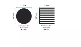
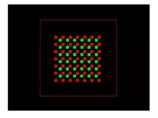
FPIX - Test Beam at CERN FPix. Test Beam at CERN Charge Sharing Vienna Repeater Y Row X Z, B } Double Column Beam 20o ROC, PSI36: 11 double columns x 30 rows Pixels 150 x150 m2 8mm D:\LHM\2001\Presentations\Plenary Presentations\For Dan \Geometry Pixels.ppt
CERN Test Results FPix. CERN’s Test Results Charge sharing vs position Pixels at 20o to beam = 14 m over pixel 150 m 150 m Charge sharing vs position 150 m / 12 = 43 m = 46 m over pixel Pixels normal to beam D:\LHM\2001\Presentations\Plenary Presentations\For Dan \Cern Test Result.ppt
FPIX Readout Electronics FPix, Readout Electronics FPGA Token Bit Manger,TBM and Control Network Hub FED Detetor Front End Controller, FEC Single Channel Prototype
Very High Density Interconnect Very Hight Densityes. Interc. VHDI for Row of 5 ROCs Test Station
FPIX - R&D Assembly - SiDet FPix, R&D Assembly. SiDet Assembly of Detectors; NIKON measurement station. Need 672 units Assembly of Butterflies; OMIS II measurement station. Need 96 units
FPIX R&D - Survey FPix, R&D Survey Survey Blades Zeiss 500 measurement station. Need 8 units (1/2-Disk) Components
US CMS FPIXBCWS, BCWP & ACWP W. Scheduled W. Performed ACW. Performed
FPIX - BCWS Profile W. Scheduled vs. Year
US CMS FPIXSch. & Cost Performance Scheduled Performance Cost Performance
US CMS FPIX (% Comp., Cont. Use) % W. Completed % Cont. Use
FPIX - ETC Mfg EDIA M&S
SOW 01 - FPIX Rutgers Fnal Purdue
FPix Critical Path Panels Disks Space Cylinders VHDI & HDI Sensors Readout Chip Bump Bonding Assembly Plaquettes Assembly Butterflies Assembly 1/2-Disks Install Disks in 1/2-Cyl. Shipment to LHC Commissioning completed
Critical Path Analysis Critical Path Analysis • The read-out chip development sets the critical path. [responsibility of PSI] • Development of the TBM, VHDI and HDI depends on the design of the ROC. • Bump Bonding is the next most critical task.
Last Review Concerns • Concerns from last time have been addressed: • Increase engineering support for HDI, (VHDI). Done • Update the near term plan with specific milestones. Done • Devote manpower immediately to the evaluation /of a new preproduction of sensors. Done • Increase manpower on bump-bonding task. • Request was made to the funding agencies but it • has not been awarded yet.
Issues Issues • Additional manpower for bump bonding remains a pressing issue. • Mechanical engineering must be made available (from US CMS) now to prevent this task from becoming a critical one.
What we plan for the next 6 months • Submission of second prototype sensors • Testing of the first prototype TBM/CNH and FEC (FPGA), … then with FED and new sensors with final chip in Dmill • Layout of VHDI and HDI • Continue tooling for the assembly • Procure prototypes PSS for 1/2-Disk
Summary and Conclusions Summary and Conclusions • FPix effort is now moving from R&D to prototyping. • Results from a test beam at CERN confirm the expected position resolution. • Evaluation of first sensor’s submissions completed. Second submission is being prepared. • A submissions for bump bonding of blank multiple • chips is being evaluated and gives promising results. • Submission TBM/CNH chip to take place this month. • Testing of prototypes TBM and FEC (FPGA) … has started; will allow a Full System test (sensors, ROC, FED, OL, ...)