Download
1 / 28
300 likes | 452 Views
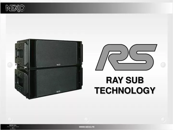
RAY SUB TECHNOLOGY. DIRECTIONAL SUBWOOFERS BENEFITS. DIRECTIONAL SUBWOOFERS. Omnidirectional pattern: Excessive low frequency level on stage (damages sound pick-up); High reverberant level in indoor venues; Environmental problems in outdoors venues. Stereo Design:

E N D
DIRECTIONAL SUBWOOFERS • Omnidirectional pattern: • Excessive low frequency level on stage (damages sound pick-up); • High reverberant level in indoor venues; • Environmental problems in outdoors venues. Stereo Design: • “Power Alley” effect related to strong Left and Right interferences. Eigen Modes: • In closed venues, room eigen modes (nulls and maximums) are dominant over source location.
d S2 S1 p1 p1 p = 0 p2 p2 + in ( ) - t=d/C DIRECTIONAL SUBWOOFERS Directional Low Frequency Radiation p = Gradient Subwoofer Block Diagram
DIRECTIONAL SUBWOOFERS Directional Low Frequency Radiation • Pressure results from front and rear generated pressures differences; • NX Controller algorithms allow up to 5 dB gain in the front zone, and 15 dB average attenuation in the rear zone (variable pattern); • Low Frequency Cut-off is determined when rear loudspeaker does not add gain in front zone; increases as cabinet depth decreases; • High Frequency Cut-off is determined when side lobes appear and on-axis level decreases; increases as cabinet depth decreases; • Usable Range: 2 to 3 octaves depending on cabinet architecture; • RS patent pending technology extends High Frequency cut-off and suppresses the Low Frequency cut-off through proper definition of radiating surfaces position and phase relationship.
RS15 On-Axis Gain: Rear (Red) – Front (Blue) - Rear+Front (Green) DIRECTIONAL SUBWOOFERS Directional Low Frequency Radiation
DIRECTIONAL SUBWOOFERS Directional Low Frequency Radiation 2xRS15 Coverage and Response
DIRECTIONAL SUBWOOFERS Directional Low Frequency Benefits • To summarize: • Rear Radiation is lowered by more than 12 dB, which benefits to stage as well as to neighbours; • Direct to Reverberant ratio is increased by nearly 6 dB (which increases Sub impact in closed venues); • Beacuse of their directional behaviour, gradient subwoofers are less sensitive to room eigen modes.
DIRECTIONAL SUB ARRAY DESIGN Choosing the right compromise Issue: • Stereophony cannot apply to VLF systems installed 20 meters apart (doublet type interferences occur on all mono signals); • No universal rule applies, this is a case to case situations where various options must systematically be explored within implementation constraints; • Sub design is experimenting, and making the right compromise. Directional sub array design rules: • Distance between subs should not be less than 0.5 meters (for proper rear to front enregy transfer), not more than 1.7 meters (so that line criteria is fulfilled up to 100 Hz) • Design is easier because consequences on stage are less
Stacked Center Sub Flown Center Sub DIRECTIONAL SUB ARRAY DESIGN CENTER MONO SUB • Advantages • No Left/ Right interferences; • Coverage constancy when flown. Drawbacks • Coverage consistancy when stacked; • Phase relation between Stereo system and center mono Sub.
Geometrically Curved Array Electronically Curved Array DIRECTIONAL SUB ARRAY DESIGN HORIZONTAL SUB ARRAY • Advantages • No Left/ Right interferences; • Coverage Control. Drawbacks • Implementation; • « Hot Spot » on stage for Curved Arrays; • Phase relation between Main System and Horizontal Array.
Stereo Omnidirectional Subs Stereo Directional Subs DIRECTIONAL SUB ARRAY DESIGN STEREO SUB DESIGN • Interferences between Left and Right are related to coverage overlap; • Overlap has to be minimized, ie Left and Right coverage have to be as independent as possible; • When using few cabinets, directional subwoofers should be rotated 30° to 45° outwards; • Interference region is then limited to the center area.
Curved Sub Array – Left Implementation Curved Sub Array – Left and Right Sum DIRECTIONAL SUB ARRAY DESIGN STEREO SUB ARRAY DESIGN • Procedure • Sub Array must be designed and experimented (one side only) to minimize overlap from one side to the other. • Advantages • Interference region is limited to the center area; • Phase relation between Main Stereo System and Sub Arrays is improved; Drawbacks • « Power Alley » effect.
Steered Sub Array – Left and Right Sum DIRECTIONAL SUB ARRAY DESIGN STEREO SUB ARRAY DESIGN • Procedure • Sub Array must be designed and experimented (one side only) to minimize overlap from one side to the other. • Advantages • Interference region is limited to the center area; • Phase relation between Main Stereo System and Sub Arrays is improved. Drawbacks • « Power Alley » effect. Steered Sub Array – Left Implementation
RS15 horizontal coverage (omni mode) RS15 vertical coverage (omni mode) RAY SUBs IMPLEMENTATION OMNIDIRECTIONAL MODE • Omnidirectional mode should be favoured when: • Sufficient depth is not available for directional implementation • Strong rear radiation is not critical • Coverage is slightly narrower along RS’s width than height
RS15 vertical coverage (direct mode) RAY SUBs IMPLEMENTATION DIRECTIONAL MODE - SINGLE • Single RS15 horizontal coverage is: • Constant 120°@-3dB / 180°@-6dB • Tilted 30° off-axis; • Single RS15 vertical coverage is: • Constant 120°@-3dB / 180°@-6dB • Symmetrical. • In directional mode, no reflecting surface should be at less than 50cm from RS15’s walls RS15 horizontal coverage (direct mode)
2 RS15 « back to back »coverage RAY SUBs IMPLEMENTATION DIRECTIONAL MODE - PAIRS « BACK TO BACK » MODE • -3 dB Horizontal Coverage decreases from: 120° @ 31 Hz to 60° @ 100 Hz • - 3dB Vertical Coverage is constant 120°
2 RS15 « alternate »coverage RAY SUBs IMPLEMENTATION DIRECTIONAL MODE - PAIRS « ALTERNATE MODE » • -3 dB Horizontal and Vertical Coverages are constant 120°
2 RS15 « face to face »coverage RAY SUBs IMPLEMENTATION DIRECTIONAL MODE - PAIRS « FACE TO FACE » MODE When set 50cm / 20’’ apart: • -3 dB Horizontal Coverage increases from: 120° @ 31 Hz to 180° @ 100 Hz • - 3dB Vertical Coverage is constant 120°
12 RS15 « alternate » unsteered column coverage RAY SUBs IMPLEMENTATION DIRECTIONAL MODE – VERTICAL COLUMNS • RS15s columns are always flown vertically (bumper at 0°, no angle between cabinets) • A 12 RS15 cluster flown at 10m / 30ft provides a +/-3 dB SPL deviation at 100Hz over 75m / 200ft while maintaining 15 to 20 dB attenuation on stage
12 RS15 « alternate » -15° steered column coverage RAY SUBs IMPLEMENTATION DIRECTIONAL MODE – VERTICAL COLUMNS • RS15s columns can be steered electronically upwards or downwards • Minimum RS15 quantity for efficient control is 4 • Coverage control increases with higher quantities • Beam steering can go up to +/-45°
RS15 ACCESSORIES TD CONTROLLERS SPECIFICATIONS
RS15 Bumper (up to 12 RS15s) RS15 Rigging Plates RS15 Wheels RS15 Dolly (up to 2 RS15s) RS15 ACCESSORIES
RS15 ELECTRONICS • NXAMP4x1 controls and powers up to 2 RS15s in all directional modes • NXAMP4x4 controls and powers up to 8 RS15s in all directional modes • NX242 Digital TDController has 46 presets to combine RS15 with PS series & GeoS series • GeoS12TD Controller features a mono output to operate RS15 in Omnidirectional Mode