Download
1 / 67
670 likes | 873 Views
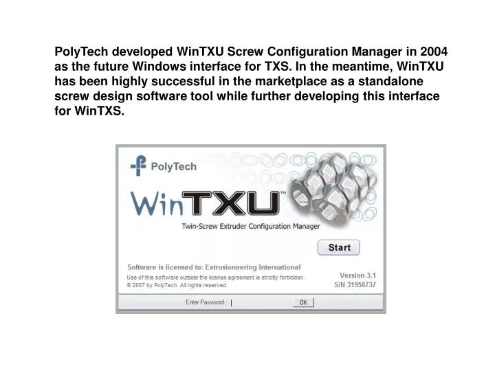
PolyTech developed WinTXU Screw Configuration Manager in 2004 as the future Windows interface for TXS. In the meantime, WinTXU has been highly successful in the marketplace as a standalone screw design software tool while further developing this interface for WinTXS.

E N D
PolyTech developed WinTXU Screw Configuration Manager in 2004 as the future Windows interface for TXS. In the meantime, WinTXU has been highly successful in the marketplace as a standalone screw design software tool while further developing this interface for WinTXS.
Select pre-defined L/D’s or specify number of barrels to create custom shaft length
Double-click on barrel name or drag-and-drop icon from above
Double-click on element name or drag-and-drop icon from above
Inventory feature applies to elements and barrels – enter current stock for each component in the table to the left. As you build a new screw design, WinTXU keeps track of remaining inventory
Change drawing colors, engineering units for storing process data Keeps track of shaft extensions – so you know where to place elements to bridge the splice
The following screen shots show the current state of development of WinTXS (1Q09) – assembly of the screw design/barrel profile is exactly the same as WinTXU. New screens have been added to WinTXS for entry of operating conditions, access of materials database and manipulation of simulation execution. For existing TXS users, all simulation parameters are the same as version 2.7xx.
Specification for breaker plate, allows WinTXS to compute pressure drop
Specification for screens, allows WinTXS to compute pressure drop
Select one of the default die plates or click on “Custom” to enter new die geometry
Adjusting coefficients are used to “tune” calculated pressure drop and temperature rise to measured/actual data
WinTXS provides a choice of view for the screw design – the “mixed” view (shown here) or side view can be selected by clicking on these icons.
Click on the “OPTIONS” tab on the toolbar to open the options window
Some parameters, formerly defined in the TXS initialization file (TXS.ini), now are user-definable during simulation execution
Calibration Factors (formerly defined using DEBUG in OPTIONS screen) are now easily accessed during simulation execution
Enabling the “DEBUG” mode in TXS provides adjustment of melting model, heat transfer, viscosity and shear rate. Adjusting these parameters, TXS simulation results are ‘calibrated’ to match actual data for a given set of operating conditions.
Once the DEBUG parameters are identified that correlate simulation results with reality (e.g. torque, melt temp) – subsequent changes in operating parameters, screw design, screw diameter, use these same values! Calibration Factors are the single largest advantage between TXS and all other simulation software products currently available
These parameters were formerly defined in the TXS initialization file (TXS.ini), now are user-definable during simulation execution
These parameters were formerly defined in the TXS initialization file (TXS.ini), now are user-definable during simulation execution
Head pressure can be calculated from die geometry or input as a process parameter.
Material selection/editing, formerly done using TXM, is now selected using the ‘Materials’ tab on the WinTXS toolbar
Click on Generic Viscosity button to create a new resin with specified viscosity.
TXS can simulate using “generic” material properties – select generic material type (e.g. PP, LDPE, PA6, PC, etc.) and specify melt flow rate. This unique feature, combined with Calibration Factors (DEBUG parameters) can provide quick and relatively accurate results without having actual material characterization – simulation results can be adjusted to match actual machine performance (torque, melt temp, etc.)
List of “generic” resins which can be used for simulation – cont’d