Download
1 / 60
610 likes | 1.08k Views
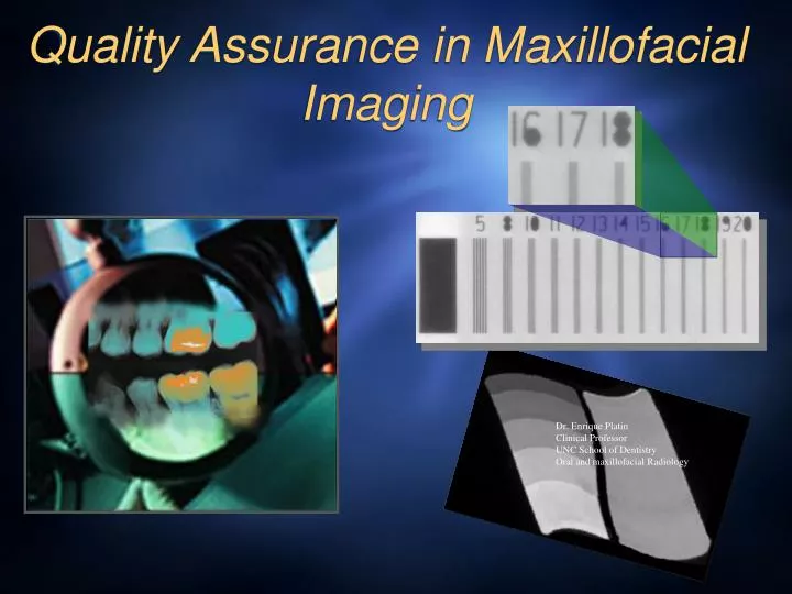
Quality Assurance in Maxillofacial Imaging. Dr. Enrique Platin Clinical Professor UNC School of Dentistry Oral and maxillofacial Radiology. Quality Assurance in Oral & Maxillofacial Radiology. Quality assurance comprises all of the management practices

E N D
Quality Assurance in Maxillofacial Imaging Dr. Enrique Platin Clinical Professor UNC School of Dentistry Oral and maxillofacial Radiology
Quality Assurance in Oral & Maxillofacial Radiology Quality assurance comprises all of the management practices instituted by the dentist to assure that every imaging procedure is necessary and appropriate, the recorded information is correctly interpreted and the examination results in the highest image quality and lowest possible radiation exposure, cost and inconvenience to the patient.
Benefits of quality Assurance • Improved diagnosis • Reduced radiation exposure to patients • More reliable equipment function • Time savings • Cost savings
Areas of radiography that should be monitored to promote consistency in image production • X-ray machine • Chemical & electronic processing • integrity if image receptors • Viewing conditions
Patient exposure and dose • There are no limits for diagnostic exposure • Know benefits and hazards • Know patient selection criteria • ALARA (As Low As Reasonably Achievable) This is the guiding principle of radiation protection everywhere including the dental office And……GET THE MOST INFORMATION FOR THE LEAST RADIATION
Use & prescription of radiographs Radiographic examination shall be performed only when indicated by patient history, physical examination, or laboratory findings (3.1.1) http://www.ada.org/prof/resources/topics/radiography.asp NCRP report No. 145
Monitoring devices • If monitoring devices are used they should be worn at waist or collar level only while working. • Devices should be stored at work in a radiation free area.
Film Holding Devices • Reduce finger exposure • Reduce number of re-takes
X-ray output and representative exposure Kilovoltage accuracy Half Value Layer (filtration) Exposure reproducibility Milliamperage linearity Beam alignment & diameter of x-ray field Tube head stability Assessment of x-ray units recommended parameters to check American Academy of Oral and Maxillofacial Radiology American Dental Society • Check yearly
X-ray output and representative x-ray exposure test This test evaluates the reproducibility of the x-ray output. It measures the amount of radiation at cone tip for a given kilovoltage, milliamperage, time, and distance. This test can be used to assess compliance with acceptable exposure ranges used for D and E films (see chart) and to make longitudinal comparisons of exposure values.
Position indicating device (PID) test Patients can be exposed to a great deal of unproductive radiation if the x-ray tube is misaligned or the diameter of the Position Indicating device (PID) “tube” exceeds federal guidelines. The guidelines state that if the source-to-skin distance is 18 centimeters or more, the x-ray field at that distance should be confinable in a circle of no more than 7 centimeters, (2.75 inches) in diameter.
Procedure To check the beam alignment and the diameter of the PID do as follows. Place a film large enough to cover the diameter of the PID on a flat surface, or arrange four No. 2 films in a cross pattern as shown above; place the PID flush to the films so that approximately half of each film is covered and make an exposure to blacken the films.
Results Process the films and arrange them in the same pattern as exposed. If the exposed area is greater than 2.75 inches in diameter, the PID opening is too large and should be replaced. If the exposed area is out of alignment with the circumference of the cone, the diaphragm in the collimator may be mal-positioned and the problem should be corrected. In the above example the PID tested falls within the guidelines. Diameter = 2.56”
Stability of tube head The suspension of the tube head and retractable area must be stable in all positions so that motion artifacts can be minimized. To check for stability, fully extend the tube head and arm, then observe for signs of drift or vibrations when the tube head is released. Any instability should be corrected by adjusting the suspension arm according to the owner’s manual.
Chemical processing conditions Studies have shown that poor processing conditions are responsible for a large percentage of radiographic re-takes. Thus, a reduction in the re-take rate can have a significant reduction in radiation exposure to patients. This is significant, since dental practitioners in the U.S. are responsible for exposing over 600 million intraoral dental films and over 17 million panoramic images per year. Today 61% general dentists and 73% specialists own panoramic units. (American Dental Association ‘s Survey Center.The 200 survey of dental practice-characteristics of dentists and patients. Chicago, Il. American Dental Association:2002)
Processing pitfalls (automatic processor) Dark images can result from high developer temperatures, long development times or overactive developers. Check the thermostat, adjust it if necessary. Also, inspect the transport system for excessive wear of the gears and sprockets, and check the roller alignment and lubrication. Check the replenishing mechanism as the developer may be overactive. High water temperatures can also be responsible for dark films. Periodically check mixing valve adjustment and correct settings if appropriate.
Conversely, light films may occur if the developer or water temperature is too low, the development time is too short, or there is a decrease in developer activity. To assess developer activity, run a strip test and check for the possibility of contaminated or exhausted solutions.
Films could turn green-orange-brown from weak fixer solutions or when stained by an oxidized developer, or by improper washing. Check the replenishment mechanism and replenish or replace solutions if necessary.
Safelighting Safelights provide adequate lighting without fogging the film. A light emitting diode LED safelight or universal safelight filter such as the kodak GBX is recommended for both intraoral and extraoral films. The wattage of the bulb should not exceed 15 and should be placed at least 4 feet away from the working surface.
Procedure Safelights should be evaluated every six months. Proceed by exposing a #2 film to radiation using a very low exposure time (the lowest setting on your machine). Turn off all the lights including the safelights. Look for light leaks, these must be eliminated. Then turn on the safelight/s, open the package of the pre-exposed intraoral filmand place it on the counter where you normally open your films. Place a few coins on top of the film (as shown above) and wait two minutes before processing the films.
Results Examine the processed film and if no image of the coins are present, it can be assumed that the safelight is safe. If images of the coin appear on the film (as seen above), the safelight/s need to be replaced. As a rule of thumb, if a safelight is on for 8 hours each day, replace it every 3 years.
Automatic processing During automatic processing, the film is transported through the developing, fixing and washing stages at controlled speeds. Most mechanical processors use roller transport modules and specifically formulated chemistries. The film is not rinsed between the development and fixing cycles. Chemistries are manufactured in concentrate form (requires mixing) and Ready-to-use (does not require mixing). Ready mixed chemistries are the most widely used.
In automatic processing, the temperature of the chemicals is thermostatically controlled and the processing time is regulated by the speed of the rollers in the transport mechanism. Always follow the recommended processing temperatures provided by the manufacturer
Automatic Processing Time/Temp method Temp. 810 830 850 Time 5 min 4 1/2 min 4 min
Chemical Replenishment Chemical solutions should be replenished daily by adding 8 ounces (236 ml) of developer and fixer to maintain optimal concentration. This should be done regardless of the levels of chemicals visible in the tank. (It may be necessary to remove some of the existing solutions before adding replenisher. This prevent solutions in tanks from overflowing.
Chemical replenishment To maintain the stability and consistency of the processing chemicals, replenish developer and fixer solutions daily. For intraoral film processors without automatic replenishment, use 8 oz. (236 mL) ofreplenisher solution daily, even if no films are processed. This is based on an average daily run of 20 to 30 intraoral films. If you process more than 30 intraoral films per day, you should increase the amount of daily replenisher at a rate of .25 fluid ounces (7 ml) per additional film processed. For example, 50 intraoral films per day would require that 5 additional ounces (140 ml) be added to the daily 8 ounces, a total of 13 ounces (376 ml).
Processing QC Optimal processing quality control requires the use of a sensitometer and a densitometer, however in the average dental office, QC can be accomplished with the use of monitoring strips as described in the next two slides.
Dental Radiographic Normalizing and Monitoring Device The DRNMD has a reference (strip) that can be used to compare the films that are exposed daily to monitor processor performance. Follow the instruction on the tool to perform QC. Daily strip Comparison of strip with reference Image of reference step wedge Dental Radiographic Normalizing & Monitoring Device http://www.cspmedicalstore.com/s.nl/sc.2/category.1628/.f
Preventive maintenance Although monitoring film chemistry with film strips is an effective way to track chemistry performance, processor upkeep and care are probably more important. Processors should be cleaned at every solution change. This should include inspecting all working parts and lubricating mechanism where indicated.
At each solution change • Always fill the fixer tank first and the developer tank second. This will prevent contamination of the developer while the fixer tank is being filled. • After filling up the processor, turn it on and let it reach the pre-determined operating temperature before developing films.
Processor Daily care At the end of the day, remove the main cover, the developer and fixer covers (unless otherwise stated by the manufacturer) and allow the processor to aerate. This prevents condensation droplets from forming under the covers and drip to the rollers resulting in film artifacts.
Maintain a log documenting changing of solutions, any problems that were encountered, and any corrective action/s taken.
Helpful checklist for automatic processing • Clean tanks and rollers thoroughly with a non-abrasive brush to remove chemical deposits and contaminants. Use a bland soap or commercial cleaner. • Rinse rollers thoroughly to remove any trace of soap or cleaner. • Inspect rollers, gears, and turning mechanism for signs of wear.
Summary 1. Clean processors regularly 2. Replenish solutions daily 3. Check dev. temperature daily 4. Perform Q.C. daily
Maintain accurate records to document maintenance and interventions.
Screens and films The selection of intensifying screens and radiographic film should result in a system that produces the highest diagnostic yield with the least possible amount of radiation to the patient and operator. Today, this is possible with the faster-speed systems that require short exposure times.
Intraoral film Currently there are two film speeds available for intraoral imaging, Speed Group D, and speed groupF. Group D film is the most widely used. It provides high contrast, fine detail and excellent image quality. Group F is more sensitive to radiation exposure requiring only about 60% less radiation than D. A review of the scientific literature has shown that these two films produce equivalent diagnostic yields. On that basis the radiology community highly recommends the use of Fspeed film.
Extraoral film Extraoral or screen film is primarily designed to be used with intensifying screens. The selection of the film should be based on the clinical application. Ideally, one should select the most sensitive system without compromising diagnostic quality.
Film selection When selecting a film, strong consideration should be given to films containing emulsions which employ flat tabular grains of silver halide. Tabular grains gather more light and by design result in an increase in image sharpness.
Soft tissue In addition, the object of the examination should be factored in, for example, in cephalometric radiography where bone and soft tissue visualization are important a wide latitude film should be selected. In temporomandibular joint radiography where bone detail is of particular importance, a high contrast film is more useful.
Intensifying screens Intensifying screens should be selected based on their conversion efficiency (converting x-ray energy into light energy). Screens using Rare Earth phosphors should be favored over screens that use Calcium Tungstate phosphors. Rare earth phosphors have a higher conversion efficiency, and can be four times as efficient as calcium tungstate phosphors. That means that they require one fourth of the x-ray energy to produce the same amount of light energy produced with Calcium Tungstate phosphors.
Spectral matching Film should be sensitive to the light emitted by the screen’s phosphor. In the case of Calcium Tungstate, a blue-light-sensitive film should be selected. In the case of Rare Earth phosphors, a green-light-sensitive film should be selected. This is essential in creating the ideal spectral match to maximize the efficiency of the system.
Cleaning intensifying screens Cassettes should be cleaned and inspected for light leaks and artifacts. A screen cleaner, mild soap and water or denatured ethyl alcohol may be used as substitutes. The following procedure is suggested for cleaning cassettes: • Open cassette. • Look for worn or stain areas. • Dampen a clean cotton ball or gauze with cleaner. • Wipe one screen at a time • Wipe each screen with dry cotton ball or gauze • Leave cassette open until dried
After each cleaning apply antistatic solution to reduce static electricity artifacts and leave the cassette open until the screens are completely dried.
Film storage Unexposed and unprocessed film should be kept in a cool, dry place. High temperatures decrease contrast and increase fog. Ideally, film should be stored at temperatures ranging between 50 and 700 F (100 and 210 C) and between 30 and 50 percent relative humidity. Films should be used before their expiration date.
Film handling Improper film handling can result in artifacts such as streaks, lines, and marks that could interfere with the diagnostic quality of the image. Films should be handled with care. Avoid bending or touching them with wet hands. Handle film by the edges and protect them from potential fogging sources.
Film artifacts The crescent or half-moon artifact observed in this example resulted from finger nail pressure. Avoid putting pressure on the film or making sharp bends, grasp film by its edges.
Static electricity is responsible for electrical discharges on the film. It produces a tree-like artifact or smudge marks. Prevent static electricity by controlling humidity during the winter months. Other potential sources of static electricity come from uniforms made of polyester materials, and rugs. Static electricity can also be caused by careless handling, such as by rapidly pulling films from their containers.
Film fog results from unsafe light, white light exposure, overactive film chemistry or expired films. This film was exposed to white light when the film packet was accidentally opened outside of the darkroom. The dark area represents light exposure. Other potential sources of film fog are light leaks, placing the daylight loader under bright lights, and from faded safelight filters.