Download
1 / 22
220 likes | 317 Views
Chemistry 140 a Lecture 11 Surface, Bulk, and Depletion Region Recombination. Quasi Fermi Levels. For calculations, it would be convenient to assume flat QFLs within a certain region, Δ x, under study. Then, the driving force for recombination would be equal everywhere. When are QFLs flat?

E N D
Chemistry 140 aLecture 11Surface, Bulk, andDepletion RegionRecombination
Quasi Fermi Levels For calculations, it would be convenient to assume flat QFLs within a certain region, Δx, under study. Then, the driving force for recombination would be equal everywhere. When are QFLs flat? When Δn or Δp is constant within Δx.
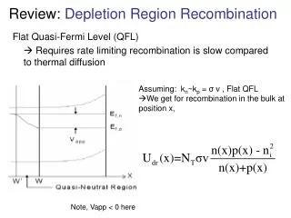
Flat QFLs • QFLs are flat in the bulk when: • Recombination at any position x is slow compared to thermal diffusion EF,n EF,0 EF,p
Flat QFLs • QFLs are flat in the bulk when: • Light excitation is uniform or light excitation is not uniform but diffusion of carriers flattens QFLs e- e- e- e- e- e- e- e- hν h+ h+ h+ h+ h+ h+ h+ h+ t = 0 non-uniform QFLs t = t1
Flat QFLs e- e- e- e- e- e- e- e- hν h+ h+ h+ h+ h+ h+ h+ h+ t = 0 t = t1 If t1, the time it takes for a uniform distribution of carriers to occur via diffusion, is less than τbr, τsr, or τdr, then the QFLs are flat.
Diffusion Time in Si e- e- e- e- h+ h+ h+ h+ d = 300 μm For recombination greater than about 25 μs, we can assume flat QFLs.
Depletion Region Recombination Let’s examine the depletion region after applying a bias Vapp: Vapp EF,n EF,0 EF,p EF,0 Vapp W W W’ The new effective depletion region is W’ < x < 0. W to W’ is a quasi-neutral region, and there is no field there. It is like the bulk, except EF,p changes with x. Quasi Fermi levels are flat within this new depletion region.
QFLs Not Flat For flat QFLs in the depletion region, recombination at the surface must be slow relative to diffusion of carriers. If surface recombination is fast relative to diffusion of carriers, QFLs will not be flat: EF,n EF,p
n(x) and p(x) Vary with x The recombination rate in the depletion region is not like in the bulk or on the surface. We now need to plug in n(x) and p(x) and integrate over 0 to W. EF,n EF,p ET W
Depletion Region Recombination Most general form: Before, we just plugged in nb = n(x) or ns = n(x) and pb = p(x) or ps = p(x). Now n(x) and p(x) change from 0 to W because of band bending. We have to integrate over all n(x) in 0 < x < W:
Depletion Region Recombination Assumptions: NT(x) = NT n1 and p1 are constants with respect to x and do not change with Vbi for a given trap: n1 = NCexp(-(EC-ET)/kT) p1 = NVexp(-(ET-EV)/kT) kn and kp are constant (this can fail since σ(ET) may vary due to ionized or unionized trap states, e.g. Zn2+ Zn+): n(x) = NCexp[-(EC(x)-EF,n)/kT] p(x) = NVexp[-(EF,p-EV(x))/kT]
n(x)p(x) Not Dependent on x If EF,n and EF,p are constant with x, then n(x)p(x) is a constant with x. n(x)p(x) = NCNV exp[-(EC(x)-EF,n+EF,p-EV(x))/kT] = NCNV exp[-(EC(x)-EV(x))/kT] exp[-(EF,p-EF,n)/kT] EC(x)-EV(x) = Eg(x) = Eg everywhere n(x)p(x) = NCNV exp[-Eg/kT] exp[-(EF,p-EF,n)/kT] n(x)p(x) = ni2 exp[-(EF,p-EF,n)/kT] -(EF,p-EF,n) = qVapp n(x)p(x) = ni2 exp[-qVapp/kT] No dependence on x. Increases in –Vapp result in n(x)p(x) > ni2.
Depletion Region Recombination Returning to U(x)… We may ignore the “1” when Vapp > 0.75 V (Vapp > 3kT/q). A harder assumption is to ignore n1 in the denominator for significant band bending. We must have either high-level injection or large Vapp.
Determination of Utotal Our assumptions: p1 and n1 are negligible kn = kp = σν
Determination of Umax There will be some Umax in this region (the depletion region) where n(x) = p(x). This is where the denominator is a minimum.
Analysis for x < xmax and x > xmax 1 1 2 2 x < xm exp(…) is negative n(x) < n(xm) extra band bending x > xm exp(…) is positive n(x) > n(xm) EF,n EF,p V = εmx = (V/cm)*cm W’ xm 0
Utotal in Terms of Umax For normally doped semiconductors, the maximum is strongly peaked away from W, so extend the integral to .
Replace exp(…) with sinh(…) if you want to include the –ni2 term we neglected. Utotal Important term. Not like thermionic emission, where it went like exp(-qVapp/kT). The e- and h+ recombination is as if we lost half of the voltage to the other carrier.
U vs. x U x …a dimensionless quantity that is the ratio of the thermal to applied voltage.