Download
1 / 40

E N D
Chapter-5 (Current and Resistance) Concept of electric current: When two ends of a source of electric energy or battery is connected by a conductor, a potential difference is created between the two ends of the conductor and electric field is created along the length of the conductor. As a result free charges i.e., electrons experience a force and flow of charge takes place. If dq is the amount of net charge passes through any surface in a time dt, current i is given by i= dq/dt. Or, dq = idt. The net charge that passes through the surface in any time interval is found by integrating the current:
Chapter-5 (Current and Resistance) If the rate of flow of charge is constant in time, the current is said to be steady or constant. Denoting the steady current by I, we simply get, I = q/t, where q is the total charge that flows in time t. Thus, we can define current as follows: The amount of charge flowing per second in a particular direction along the normal to the cross-sectional area of a conductor is called electric current. In other words, flow of charge in unit time along any point of a conductor is called electric current. According to convention, the direction along which positive charges flow is taken as the direction of electric current [Fig-1]. For negative charge the direction of electric current is opposite [Fig-2]. The S.I. unit of current is Coulomb per second called Ampere.
Chapter-5 (Current and Resistance)
Chapter-5 (Current and Resistance) Current density: Although steady current I through a conductor is same everywhere, the rate of flow of charge through a unit area of cross section may be different at different points along the conductor. To describe this flow, a term current density is introduced. The current density at a point is defined as the amount of current flows through a unit area of cross-section around that point. It is a vector quantity and is represented by the symbol j. Let S be the total surface area through which current i is flowing out and dA is an elementary area around a point where the current density is j. Then the total current that escapes the
Chapter-5 (Current and Resistance) If the current i is distributed uniformly across a conductor of cross-section area A, then j is constant for all points within the conductor and is normal to the cross-sectional area. Then the total current is, I =jA. Or, j = I/A. The S.I unit of current density is A/m2. Electron drift velocity: During flow of current, the velocity with which an electron moves from lower potential to higher potential is called the drift velocity of the electron.
Chapter-5 (Current and Resistance) The drift velocity vd of the charge carriers in a conductor can be computed from the current density j. Fig- 3 shows the conduction electrons in a wire moving to the right at a drift velocity vd. If n is the number of conduction electrons per unit volume, then the number of conduction electrons in a length L of the wire of cross-sectional area A is nAL. Therefore, the total charge q is, q = nALe, where e is the electronic charge. If this charge q flows through the conductor of volume AL in time t, then on the average the electrons cover a distance L in time t. That is t = L/vd.
Chapter-5 (Current and Resistance)
Chapter-5 (Current and Resistance)
Chapter-5 (Current and Resistance)
Chapter-5 (Current and Resistance)
Chapter-5 (Current and Resistance) Self Assesment-1: A 0.20 mm diameter copper wire is sealed end to end to a 5.0 mm iron rod and a current is sent lengthwise through them. If the current in the copper is 8.0 A, what are (a) current and current density in the iron rod, and (b) current density in the copper? [Ans:8.0A, 400 kA/m2, 254 MA/m2]. Self Assesment-2: A copper wire of 3.0 mm2 cross sectional area carries a current of 5.0A. Find the magnitude of the drift velocity for the electrons in the wire. Given that number of charge carrier per unit volume is 8.5 × 1028. [0.112 mm/s]
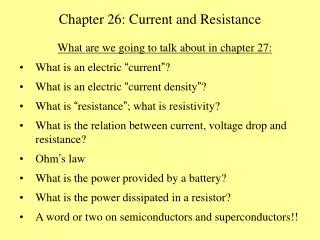
Chapter-5 (Current and Resistance) Ohm’s law, resistivity and conductivity: Let us make a circuit arrangement as shown in Fig-4 and apply a uniform potential difference across the conductor R and measure the resulting current. If the measurement is repeated for various values of the potential difference, it is found that the ratio of the potential difference to the current is always constant, provided the temperature is constant. Famous German scientist G.S. Ohm after extensive work with different conductors came to this conclusion in 1826 that the ratio of current I flowing through a conductor to the potential difference or applied voltage V between the ends of the conductor is constant.
Chapter-5 (Current and Resistance)
Chapter-5 (Current and Resistance)
Chapter-5 (Current and Resistance) Another way Ohm’s can be stated which is “ at a particular temperature, the current flowing through a conductor is directly proportional to the potential difference between the ends of the conductor”. Let another experiment be performed with the same set up but this time dimension of the conductor of the same material is increased keeping the length same. It is found that the ratio of the potential difference to the current decreases. On the other hand, if the length of the conductor is increased keeping the dimension same, the ratio increases. This ratio which is the characteristic of the conductor is called resistance. Related to resistance there is another term called the resistivity.
Chapter-5 (Current and Resistance) For a particular conductor of some metallic material is has been found that the resistance is directly proportional to length L and inversely proportional to the area of cross section A of the conductor. That is, R ∞ L when A is constant and R ∞ 1/A, when L is constant. So, R ∞ L/A, when both L and A are variable. Therefore, R = ρL/A, where the proportionality constant ρ is called the resistivity or specific resistance and is a characteristics of the material of the conductor. When L = 1m and A= 1m2, then R = ρ. Thus the resistivity of a material is defined as the resistance of the material of unit length and unit area of cross section (i.e. unit cube of the material).
Chapter-5 (Current and Resistance) In an isotropic conductor if E is the electric field inside the conductor at a point where the current density is j,then j is proportional to E. That is, j ∞ E ⇒ j = σE⇒ E = j = ρj ∴ ρ = E/j and σ = j/E. where σ is called the conductivity of the material of the conductor. Inverse of σ is called the resistivity or specific resistance of the conductor.The S.I. unit of resistivity is ohm-meter. The unit of conductivity which is inverse of resistivity is then ohm-1 meter-1 = mho/meter.
Chapter-5 (Current and Resistance)
Chapter-5 (Current and Resistance) Resistors connected in Series and in Parallel: Resistors are probably the most commonly occurring components in electronic circuits. Practical circuits often contain very complicated combinations of resistors. It is, therefore, useful to have a set of rules for finding the equivalent resistance of some general arrangement of resistors. It turns out that we can always find the equivalent resistance by repeated application of two simple rules. These rules relate to resistors connected in series and in parallel.
Chapter-5 (Current and Resistance) Resistors in series: We consider two resistors connected in series, as shown in Fig-6. It is clear that the same current flows through both resistors. For, if this were not the case, charge would build up in one or other of the resistors, which would not correspond to a steady-state situation (thus violating the fundamental assumption of this section). Suppose that the potential drop from point to point is . This drop is the sum of the potential drops V1 and V2 across the two resistors R1 and R2 , respectively.
Chapter-5 (Current and Resistance)
Chapter-5 (Current and Resistance) Resistors in parallel: We consider two resistors connected in parallel, as shown in Fig-7. It is clear, from the figure, that the potential drop across the two resistors is the same. In general, however, the currents I1 and I2 which flow through resistors R1 and R2 , respectively, are different. According to Ohm's law, the equivalent resistance Req between and is the ratio of the potential drop across these points and the current which flows between them. This current must equal the sum of the currents I1 and I2 flowing through the two resistors, otherwise charge would build up at one or both of the junctions in the circuit. Thus, I = I1 + I2 …………….(1)
Chapter-5 (Current and Resistance)
Chapter-5 (Current and Resistance)
Chapter-5 (Current and Resistance)
Chapter-5 (Current and Resistance)
Chapter-5 (Current and Resistance)
Chapter-5 (Current and Resistance)
Chapter-5 (Current and Resistance)
Chapter-5 (Current and Resistance)
Chapter-5 (Current and Resistance)
Chapter-5 (Current and Resistance)
Chapter-5 (Current and Resistance)
Chapter-5 (Current and Resistance)
Chapter-5 (Current and Resistance) Electromotive force: Inside the cell or battery charges are created due to chemical reaction travel from one terminal to another terminal. As a result, one terminal becomes positively charged and the other terminal becomes negatively charged. Due to presence of positive and negative charges in the two terminals of the cell, a potential difference appears between the terminals. The maximum potential difference that exists between the terminals of the cell, when it is disconnected from the external circuit, is called the electromotive force of the cell.
Chapter-5 (Current and Resistance) If the cell is connected to the external resistance R1, current will flow through R1.If the circuit is not disconnected or if the cell is not damaged, current will continue to flow in the circuit. That means cell is the driving force which maintain the current flow in the circuit. So, the electromotive force may be defined in another way like “The driving force which keeps or maintains the flow of current in the circuit is called electromotive force”.
Chapter-5 (Current and Resistance) To maintain current flow in the external circuit some work must be done by some external agent to transfer charges from the lower potential (negative) terminal to the higher potential (positive) terminal. The work is supplied by cell or battery. The amount of work done by the cell or battery in bringing a unit positive charge from the negative terminal to the positive terminal is the electromotive force, or e.m.f. of the cell or battery. The e.m.f. is represented by the symbol ε. Its SI unit is volts.
Chapter-5 (Current and Resistance) Thus, if the work done by the cell or battery to transfer dq amount of charge from negative terminal to the positive terminal is dW, then e.m.f. of the battery or cell is given by, ε = dW/dq. Now, let a conductor of resistance R1 be connected to a battery of e.m.f. ε, then the potential difference between the ends of the conductor is given by Ohm’s law, VA-VB = IR +Ir = (R+r)I, where r is the internal resistance of the cell or battery.
Chapter-5 (Current and Resistance)