Download
1 / 20
230 likes | 630 Views
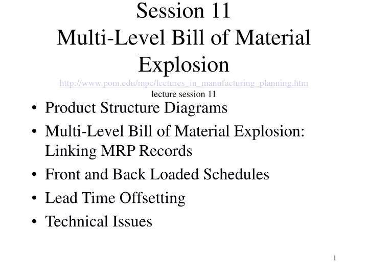
Session 11 Multi-Level Bill of Material Explosion http://www.pom.edu/mpc/lectures_in_manufacturing_planning.htm lecture session 11. Product Structure Diagrams Multi-Level Bill of Material Explosion: Linking MRP Records Front and Back Loaded Schedules Lead Time Offsetting Technical Issues.

E N D
Session 11Multi-Level Bill of Material Explosionhttp://www.pom.edu/mpc/lectures_in_manufacturing_planning.htmlecture session 11 • Product Structure Diagrams • Multi-Level Bill of Material Explosion: Linking MRP Records • Front and Back Loaded Schedules • Lead Time Offsetting • Technical Issues
Product Structure Example: P301 Computer Memory board (M) Assemble 4 RAM chips and 1 switch (S) onto a board type (X). Arithmetic board (A) Assemble 1 integrated microprocessor (Z) with 2 ROM chips and 1 switch (S) onto a board type (Y). M A
Product Structure Example: P301 Computer (Continued) Processor unit (P) Working from back to front of the box casing (B), assemble one switch (S) to the inside of each of the 4 plug connections at the back of the box. Then fit 4 memory boards (M) into the 4 identical rows of connectors. Finally, fit the arithmetic board (A) into the front connector row.
V K Product Structure Example: P301 Computer (Continued) Final Assembly The video unit (V) and the keyboard unit (K) have been preassembled (with connecting cables). Simply connect the sockets on the end of their cables to the corresponding plugs at the rear of the processor unit (P). The computer is now ready to use. P
Product Structure Example: P301 Computer (Continued) • Draw the product structure tree according to the assembly directions. • Determine low-level codes for each product. • Assume no inventory of any item. How many of each part should be available to assemble one completed unit?
Linking MRP Records: Examples The Big B Bike and Trike Shop produces two basic bikes called A and B. Each period, Paul, the owner. plans to assemble 10 A bikes and 5 B bikes. Given this information and the following product structure diagrams for A and B, fill out the MRP records for component parts G and Y for the next seven periods.
Linking MRP Records: Examples (Continued) MPS Bike B: 5 u/period Bike A: 10 u/period
Linking MRP Records: Problem 8 Part b Suppose 10 units of safety stock are required for part Y. What changes would result in the records? Would the MRP system produce any exception messages? • Exception message: period 2 below safety stock. • There will be an increase in the order in period 1 from 18 to 28 units.
Front and Back Scheduling Example Peter’s Power Tools (PPT) has just received an order for 50 PPT band saws, to be shipped at the beginning of period 9. Information concerning the saw assembly is given in this table. • Draw the product structure diagram
Saw A (2 required) B C (3 required) E (3 required) D D (2 required) F (3 required) E (2 required) D (2 required) PPT Product Structure Diagram • Draw the product structure diagram
PPT Front Loaded Schedule • Construct a Gantt chart for the new order using front scheduling logic.
PPT Back Loaded Schedule • Construct a Gantt chart for the new order using back scheduling logic.
Scheduling Explanation The front scheduling logic causes all the work to be done ahead of schedule which creates additional inventory and occupies resources that could be used on other orders. MRP applies back scheduling logic so that parts and components are completed when they are needed to fill customer orders.
Lead Time Offsetting • Precedent Relationship • Components of Lead Time • Set-up Time • Run Time • Material Handling Time • Queue Time • Staging Time • Cumulative Lead Time • Advantage of Back Loaded Schedules
Technical Issues • Low Level Coding • Indented Bill of Materials • Pegging • Cumulative Lead Time • Planning Horizon • Processing Frequency • Regeneration • Net Change