Download
1 / 38
400 likes | 577 Views
Tunnelling Introduction & Survey. HISTORY OF TUNNELLING. Earlier history is traced through mining started prior to 2000 BC Ancient tunnels were built for water supply and escape route from Forts during wars

E N D
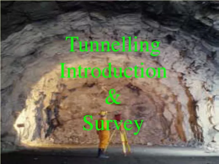
Tunnelling Introduction & Survey
HISTORY OF TUNNELLING • Earlier history is traced through mining started prior to 2000 BC • Ancient tunnels were built for water supply and escape route from Forts during wars • Pioneer tunnel of canal age constructed in 1666-81 to connect Atlantic to Mediterranean • Use of gun powder first time • Due to importance of Water transport, canal system developed in England & other countries in 18th Century leading to construction of no. of tunnels
HISTORY OF TUNNELLING (cont…) • Brunel’s Thames Tunnel was constructed between canal age and Railway age using shield • Enormous spread of Railways in Great Britain in 19th Century brought no. of tunnels. • Alpine Railway tunnels between North Europe & Italy involves new development in drilling equipment and explosives • Due to requirement of speedy construction in longer tunnels/safety requirements T.B.M. were developed which does not involve normal drilling blasting.
PRIMARY FACTORS IN SELECTION • Location/site of stations • Parameters of curve and gradient • Length of line • Balancing E/Work in Cutting & Bank • Stable sites for viaducts/Tunnels.
REQUIREMENT OF RAILWAY TUNNELS • Tunnel cross-section • Drainage • Safety from loose falls • Refugis Trolley/Man • Ventilation • Lighting
TUNNEL CROSS SECTION • Utility • SOD • Type of Rock/Soil • Method of Tunneling • Standardisation
SURVEYING • Geological Investigation recommended at preliminary survey stage itself. • Geological Investigation • Surface Mapping • Electroresistivity tests • Aerial Photogrammetry and Satellite Images are recommended for Major Projects
GEOTECHNICAL INFORMATION REQUIRED 1) Geological Description with details of lithology and variability 2) Location and Orientation of discontinuities and planes of weakness w.r.t. TUNNEL EXCAVATION • BEDDING PLANES • JOINTS • FAULT/FOLDS • SHEAR ZONES 3) In Situ Stress 4) Geomechanical properties 5) Ground water
ROCK QUALITY DESIGNATION (RQD) (BY DEERE 1964) • RQD (Percent) Quantative < 25 Very Poor 25-50 Poor 50-75 Fair 75-90 Good 90-100 Excellent 2.16” Dia double barrel diamond drill equipment
ROCK QUALITY DESIGNATION (RQD) (BY DEERE 1964) CONT…. • QUICK INEXPENSIVE LIMITATIONS: By disregarding - Jt. Orientation - Tightness - Gouge material
Topographical survey • Initial corridors on maps 1:50,000 or 1:25,000 • Confirmation on maps 1:10,000 or 1:5,000
Ground survey • Setting out alignment on ground • Establishing relationship – Network • Triangulation • Traversing • Trilateration • Accuracy For short drives 1in 20,000 equals to 10 sec • Accuracy For long drives & higher precision 1in 2,00,000 • Can be achieved with 1 sec theodolite but practically only 1 in 60,000 possible
Ground survey • Levelling • Accuracy of 2mm / Km • Closing error of 3mm over 1 Km • For large circuits square root of number of sights • Back sight & Fore sight should be equal & of moderate length i.e. not more than 35 m. • Both scale of staff should be checked with accuracy of 0.15 mm
Setting out & Control • Setting out Base line at each working face • Underground Survey • Horizontal Alignment • Vertical Alignment
Control of Tunnel Drive • Initial survey for Setting out • Primary control Survey • Face control • Control points at every 500 m & 100 m
Tunnel Profiling Methodes • Regular spaced cross sections are taken • Information is used for • Estimation of clearances • Checking alignments • Determination of volumes of excavation • Determination of lining materials • Compilation of inventories and “As built” drawings • Monitoring changes • Monitoring progress of projects • Indication of structural failures
Methods of tunnel profiling • Contact methods • Non-contact methods • Manual • automatic
Contact methods • Probe and proctor method • Finger probe method • Tape extensometers method
Non-contact methods (manual) • Theodolite / EDM Tachometer • Optical Tachometer • Laser Tachometer • Photogrammetry • Mono / stereo • Light sectioning
Non-contact methods (automatic) • Reflectorless EDM • Automated theodolites • Railway gauging train
Light sectioning cont. • The light sectioning method was developed to quantify the volumes of rock involved. The method makes use of a radially projected then beam of light.
Light sectioning cont. • When projected in a tunnel, and imaged from a distance, the beams highlights the profile of this drift in a Canadian mine.
Light sectioning cont. • Image processing techniques can be used to calculate the volume of excavated material
Light sectioning cont. • Image processing techniques can be used to measure overbreak, as in this example from the Mexican tunnels. The measured tunnel profile is overlain onto the design profile. Overbreak (blue) and underbreak (yellow) are defined outside of the of the specified tolerance (green) of the design..
Major features • Coaxial focusing system reflectorless EDM • High-precision ±(5+3ppm x D)mm reflectorless EDM • 0.5 sec. high-speed tracking measurement time • Can be used with standard prisms and reflector sheets • Long distance measurement possible(5km/16,400 ft. for a single prism) • Offers powerful DTM-350 features, suitable for a wide variety of surveying applications: • Superior function on-board data recording system (with 5,000-point data memory) • Light, compact design