Download
1 / 22
340 likes | 1.09k Views
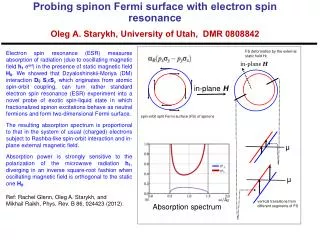
Application Solutions of Plane Elasticity Professor M. H. Sadd. Airy Representation. y. x. Biharmonic Governing Equation. Traction Boundary Conditions. S. R. Solutions to Plane Problems Cartesian Coordinates. y. T. T. 2c. x. 2l. Uniaxial Tension of a Beam. y. M. 2c. M. x.

E N D
Application Solutions of Plane Elasticity Professor M. H. Sadd
Airy Representation y x Biharmonic Governing Equation Traction Boundary Conditions S R Solutions to Plane ProblemsCartesian Coordinates
y T T 2c x 2l Uniaxial Tension of a Beam
y M 2c M x 2l Pure Bending of a Beam Note Integrated Boundary Conditions
w wl wl 2c x y l/c = 2 l/c = 3 l/c = 4 Dimensionless Distance, y/c 2l x/w - Elasticity x/w - Strength of Materials Bending of a Beam by Uniform Transverse Loading
w wl wl 2c x y 2l Bending of a Beam by Uniform Transverse Loading Note that according to theory of elasticity, plane sections do not remain plane For long beams l >>c, elasticity and strength of materials deflections will be approximately the same
y P x N 2c L Cantilever Beam Problem Displacement Field Stress Field
p x A B L y Cantilever Tapered Beam Stress Field x = L x = L
Airy Representation Biharmonic Governing Equation Traction Boundary Conditions S R y r x Solutions to Plane ProblemsPolar Coordinates
p2 r1 p1 r2 r1/r2 = 0.5 /p r /p r/r2 Dimensionless Distance, r/r2 Thick-Walled Cylinder Under Uniform Boundary Pressure Internal Pressure Case
y a T T x r/a Stress Free Hole in an Infinite Medium Under Uniform Uniaxial Loading at Infinity
T T T T T T Unaxial Loading T Biaxial Loading T T Biaxial Loading Stress Concentrations for Other Loading Cases K=3 K=2 K=4
y a x b Stress Concentration Around Elliptical Hole ()max/S Circular Case (K=3)
Y X x r C y xy/(Y/a) y/(Y/a) Dimensionless Distance, x/a Half-Space Under Concentrated Surface Force System (Flamant Problem) Normal Loading Case (X=0) y = a
y r x = 2 - Notch-Crack Problems Contours of Maximum Shear Stress
Two-Dimensional FEA Code MATLAB PDE Toolbox • - Simple Application Package For Two-Dimensional Analysis Initiated by Typing “pdetool” in Main MATLAB Window • Includes a Graphical User Interface (GUI) to: - Select Problem Type - Select Material Constants - Draw Geometry - Input Boundary Conditions - Mesh Domain Under Study - Solve Problem - Output Selected Results
FEA Notch-Crack Problem (vonMises Stress Contours)
P r a b Theory of Elasticity Strength of Materials a/P = /2 b/a = 4 Dimensionless Distance, r/a Curved Beam Problem
Disk Under Diametrical Compression P = D P Flamant Solution (1) + + Radial Tension Solution (3) Flamant Solution (2)
y P r1 1 x r2 2 P Disk Under Diametrical Compression = + +
Photoelastic Contours Theoretical Contours of Maximum Shear Stress Finite Element Model(Distributed Loading) (Courtesy of Dynamic Photomechanics Laboratory, University of Rhode Island) Disk ResultsTheoretical, Experimental, Numerical