Download
1 / 20
231 likes | 1.49k Views
A VISUAL AID TO PYROMETRY COMPLIANCE (A Guide To An Acceptable TUS Report) February 2010. Reasons for the TUS Report Visual Aid. To help address the top pyrometry findings Feedback from HT suppliers in answering NCR’s:

E N D
A VISUAL AID TO PYROMETRY COMPLIANCE (A Guide To An Acceptable TUS Report) February 2010
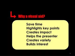
Reasons for the TUS Report Visual Aid • To help address the top pyrometry findings • Feedback from HT suppliers in answering NCR’s: • Struggle to grasp AMS 2750 requirements; particularly newer suppliers. • Provides a snap-shot of where the requirements come from in AMS 2750D. (IT DOES NOT INCLUDE ALL REQUIREMENTS.) • Visual aid for newer suppliers • Can be used as a checklist • Information for the auditor • Condenses many of the requirements onto one page • Feedback from Nadcap auditors
Top Pyrometry Findings The following AC7102C checklist questions had the most occurrences for NCRs written from Oct 16, 2006 through Jan 3, 2008: Checklist Question (AC7102E): Occurrences: 10.8.7.1 29 9.20.1 26 9.20.2 24 10.2.10 / 10.2.11 23 10.3.1 22 9.18.1 21 10.8.1.3 17 10.4.4 16 10.6.2 16 9.24.4 16 6 out of the 10 are from TUS
Top Pyrometry Findings • Question 10.8.7.1 Does documentation of the performed TUS include as a minimum: (requirements of the TUS report). • Questions 10.2.10 / 10.2.11 Do procedures specify when correction factors are to be used? Is the application documented in clear and unambiguous terms? • Question 10.3.1 Do all test instruments have a digital display and output, and meet the readability, calibration frequency, and accuracy requirements of Table 3 of AMS 2750D or more stringent customer requirements? • Question 10.8.1.3 Do procedures and documentation exist to demonstrate that test frequencies and test temperatures meet AMS 2750D Table 8 or 9, or more stringent customer requirements, on both a periodic and annual basis?
Top Pyrometry Findings • Question 10.4.4 Do instrument calibration records and stickers show conformance to the requirements of AMS 2750, or more stringent customer requirements? • Question 10.6.2 Are the furnaces instrumented for the Instrumentation Type identified by the supplier? • Number 1 TOP FINDING 10.8.7.1 The temperature uniformity survey data and summary reports for all aerospace approved furnaces did not include the test instrument calibration correction factors in accordance with AMS2750D, paragraph 3.5.20.1.
Temperature Uniformity Survey Report BACK TO TABLE
I. Thermal Processing Equipment • Identification: • Unique identifier tying the furnace to calibration history and data (par 3.5.21.1). • Can use name and/or number. • Work Zone Dimensions and Volume: • To define the qualified work zone boundaries and to determine the number and location of TUS thermocouples (par 3.5.13.2.1, 3.5.12.2.2, 3.5.13.2.3,Table 11). BACK TO TABLE
I. Thermal Processing Equipment • Furnace Atmosphere: • Defines the atmosphere that will be used for the TUS. It shall be the normal atmosphere used in production except as noted in paragraph 3.5.11. • Load Condition: • Load condition (rack, production load, etc.) must be established during initial TUS so that all subsequent surveys shall be conducted in like manner (par 3.5.10) . BACK TO TABLE
I. Thermal Processing Equipment • TUS Fixture or Load Identification: • Used to determine that the qualified work zone meets the required uniformity range. • Ties the initial TUS to all subsequent periodic/annual surveys (par 3.5.10, 3.5.10.1, 3.5.10.2). • Detailed diagram, description or photograph(s) required (par 3.5.21.1). • Furnace Class and Instrument Type: • The controlling processing specifications determine the minimum required temperature uniformity range and defines the Class. (par 3.3.1). • Defines the SAT and TUS intervals, the instrument/sensor configuration/resolution, (par 3.3.1, 3.3.1.1 - 3.3.1.6; Tables 3, 6, 7, 8, 9). BACK TO TABLE
II. Furnace Instrumentation • Control, Monitoring, Recording Equipment must be calibrated: • Accuracy is based on type of instrument (analog or digital). • Calibration interval is based on the furnace class and on the type of instrument (Table 3, Note 5). • Control, Monitoring, Recording Equipment must be tested for sensitivity: • Minimum sensitivity is based on furnace class (Table 3, Note 4). • Definition: Thetemperature change in the input that is required to activate a change on the instrumentation. BACK TO TABLE
III. TUS Test Instrument • A TUS test instrument shall be: • Digital • Have a minimum readability of 1oF or 1oC (par 3.2.3). This includes recording test instrumentation. • Maximum calibration frequency is 3 months (Table 3). • Correction factors: • Correction factors must be included in the test instrument calibration (par 3.5.20.1). BACK TO TABLE
IV. TUS Thermocouples • Type: • When choosing the type of sensor, consider whether it will be expendable/nonexpendable, base or noble metal. This determines usage and recalibration requirements (par 3.1.5.2, 3.1.1.10, Table 1). • Correction Factor: • Be sure to understand whether the certification is reporting error deviation or correction factor. • Their application is to be documented in clear and unambiguous terms. • No extrapolation above or below calibration data listed on the certifications. BACK TO TABLE
IV. TUS Thermocouples • Calibration Report Number: • Thermocouples shall have a certificate of compliance as stated in paragraph 3.1.1.1. • Calibrated Range: • Sensors shall be calibrated in the temperature range within which they are to be used (par. 3.1.1.3). • Interval between any two test points must be not greater than 250 deg. F or more stringent customer requirement (par. 3.1.1.3, Table 1.) • Number of Thermocouples: • Based upon work space volume and furnace class (Table 11). BACK TO TABLE
V. Furnace Thermocouples Required by Instrument Type • Depending on instrument type, load sensors and/or high and low sensors are required for the TUS. • Attach to or insert load sensors to heat sinks that meet 3.5.10.1. • Maintain same method of surveying as performed for initial TUS. BACK TO TABLE
VI. Diagram of Thermocouple Location and Identification • Sensor location must be unambiguous. This is required so as to properly analyze the TUS data (par 3.5.21). • Show location of furnace sensors required by applicable instrumentation type such as high/low sensors (par 3.5.13.3.2). • A detailed diagram, description, or photograph(s) of any load or rack used. BACK TO TABLE
VII. TUS Test Information • Next TUS Due Date: • Frequency based upon furnace class and instrument type as defined in Table 8 or 9. • Qualified Operating Range: • Define the qualified operating range(s) with 600 deg. F intermediate ranges max. (par 3.5.5 and 3.5.6). • Initial or Periodic TUS: • Establishes what set temperatures can be used for the TUS. • At least once within each calendar year, periodic tests to be performed at minimum and maximum of each qualified operating temperature range (par 3.5.6). BACK TO TABLE
VII. TUS Test Information • Time Stabilized / Start Time: • It is required that TUS data must be collected from all furnace sensors required by the applicable instrument type (par 3.5.13.3.2). • TUS data collection shall begin before the first furnace or TUS sensor reaches the lower tolerance limit of each test temperature (par 3.5.13.3.1). • Stabilization, recovery or recurrent temperature pattern must not exceed the time limit specified in any applicable process specification (par 3.5.17.1). BACK TO TABLE
VII. TUS Test Information • Finish Time: • TUS sensors shall be recorded at a frequency of at least one set of all readings every two minutes for the duration of the survey (par 3.5.13.3.2 and 3.5.13.3). • Duration of the survey is 30 minutes minimum after stabilization (par 3.5.13.3). • Recording frequency of furnace sensors required by the applicable instrumentation type may be up to 6 minutes as defined in paragraph 3.5.13.3.2. BACK TO TABLE
TUS Report Summary Furnace UniformityFurnace uniformity resulting from the TUS: +XX / -XX deg F.Overshoot: None observed.******************************************************************************Report SummaryAre the TUS test results acceptable per applicable specification requirements? A “No” response requires explanatory comment in the notes section. Yes ___ No ___Notes:1) Furnace TUS test results were within the required ±XXºF tolerance. No adjustments were necessary.______________________________________Signature of Technician and Date______________________________________Quality Assurance Acceptance and Date